About the Project
The AutoSDV project, namely the Autoware Software-Defined Vehicle, features an affordable autonomous driving platform with practical vehicle equipment for educational and research institutes. This project allows you to build a self-driving platform at home and use it in real outdoor road environments. Driven by Autoware, the leading open-source software project for autonomous driving, it gives you great flexibility and extensibility with the vehicle software.
AutoSDV provides a complete stack from hardware specifications to software implementation, offering an accessible entry point into real-world autonomous systems using industry-standard tools and practices.
|
|
|
| Robin-W Solid-State LiDAR Kit | Velodyne 32C LiDAR Kit | Cube1 LiDAR + MOXA 5G Kit |
Citation
If you use AutoSDV in your research or educational projects, please cite our work using the following BibTeX entry:
@misc{autosdv2025,
  author = {Hsiang-Jui Lin, Chi-Sheng Shih},
  title = {AutoSDV: A Software-Defined Vehicle Platform for Research and Education},
  year = {2025},
  institution = {National Taiwan University},
  url = {https://github.com/NEWSLabNTU/AutoSDV},
  note = {Accessed: 2025-04-28}
}
Platform Models
| Feature | Base | 360° LiDAR | Solid-State | Connected |
|---|---|---|---|---|
| LiDAR Model | - | VLP-32C | Robin-W | Robin-W |
| LiDAR FOV | - | 360° × 40° | 120° × 25° | 120° × 25° |
| LiDAR Range | - | 100m | 150m | 150m |
| Localization | Vision only | NDT ready | Development needed | Development needed |
| Remote Operation | Manual | No | No | Yes (5G) |
| Battery Life | 40 min | 40 min | 40 min | 40 min |
- Base Model - Core platform for customization
- 360° LiDAR Model - Production-ready with Velodyne VLP-32C
- Solid-State Model - Modern LiDAR with Seyond Robin-W
- Connected Model - 5G-enabled with a solid-state LiDAR
Base Model
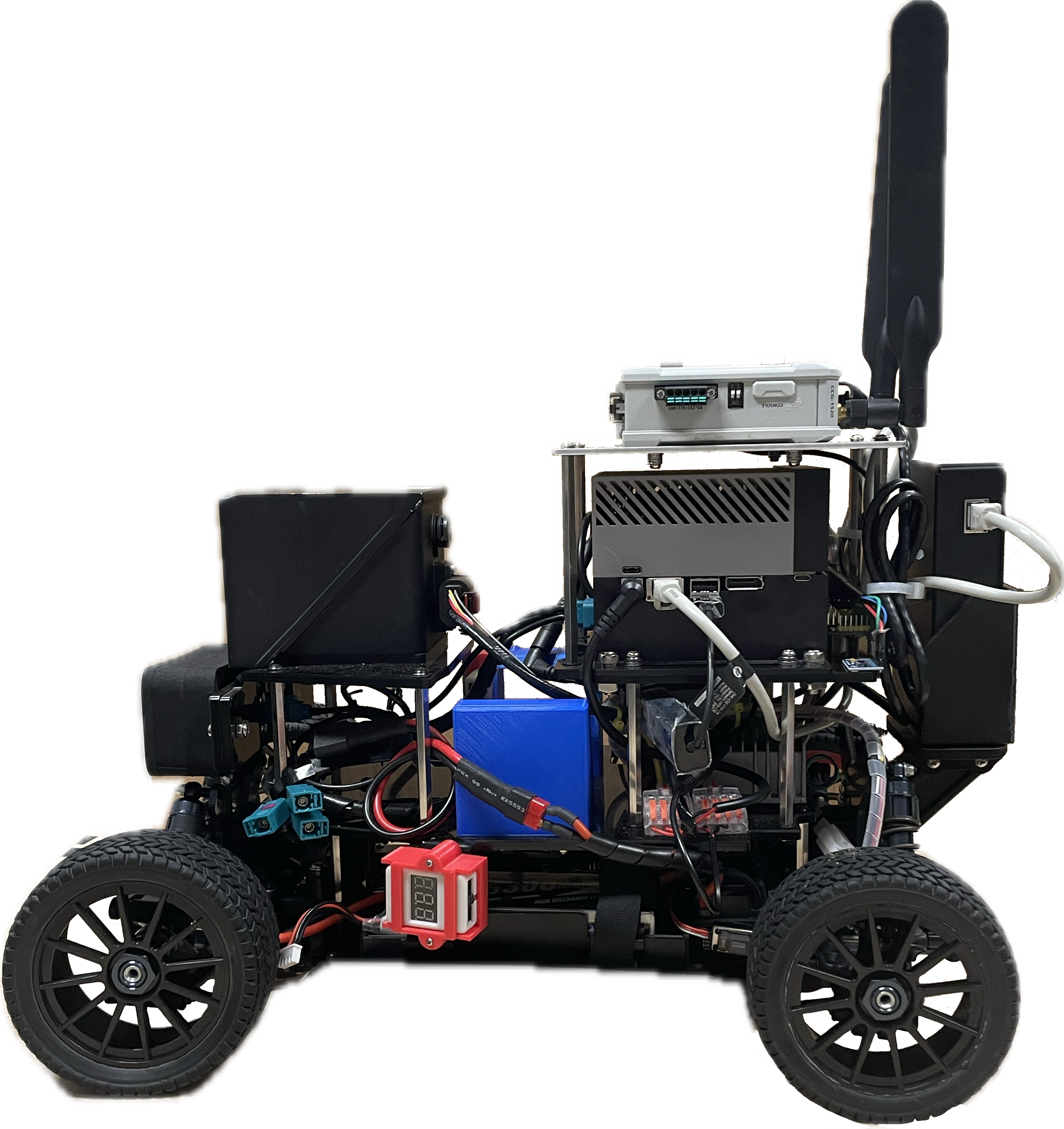
The core AutoSDV platform with compute, vision, and control capabilities. Ideal for vendors integrating their own sensors.
Core Components
| Component | Specification |
|---|---|
| Chassis | Tekno TKR9500 16×11×5" truck |
| Computer | NVIDIA Jetson AGX Orin 64GB |
| Storage | 1TB NVMe SSD |
| Camera | ZED X Mini Stereo |
| ZED Link | Capture Card for ZED |
| IMU | MPU9250 9-axis |
| Hall Sensor | KY-003 wheel encoder |
| Upper Battery | 22.2V 6S 5000mAh LiPo |
| Lower Battery | 7.4V 2S 7200mAh LiPo |
| Motor | Brushless 4274/1500kv |
| ESC | 60A Brushless controller |
| Servo | High-torque digital |
| PWM Driver | PCA9685 16-channel |
| DC-DC Converter | 24V→12V 10A |
| Circuit Breaker | 30A safety switch |
Available Interfaces
- Ethernet: 10GbE port for high-speed LiDAR connection
- USB: 4x USB 3.2 Type-A, 2x USB Type-C with USB 3.2
- GPIO: 40-pin header with I2C, SPI, UART, PWM
- PCIe: M.2 Key M and Key E slots for expansion
- Display: DisplayPort
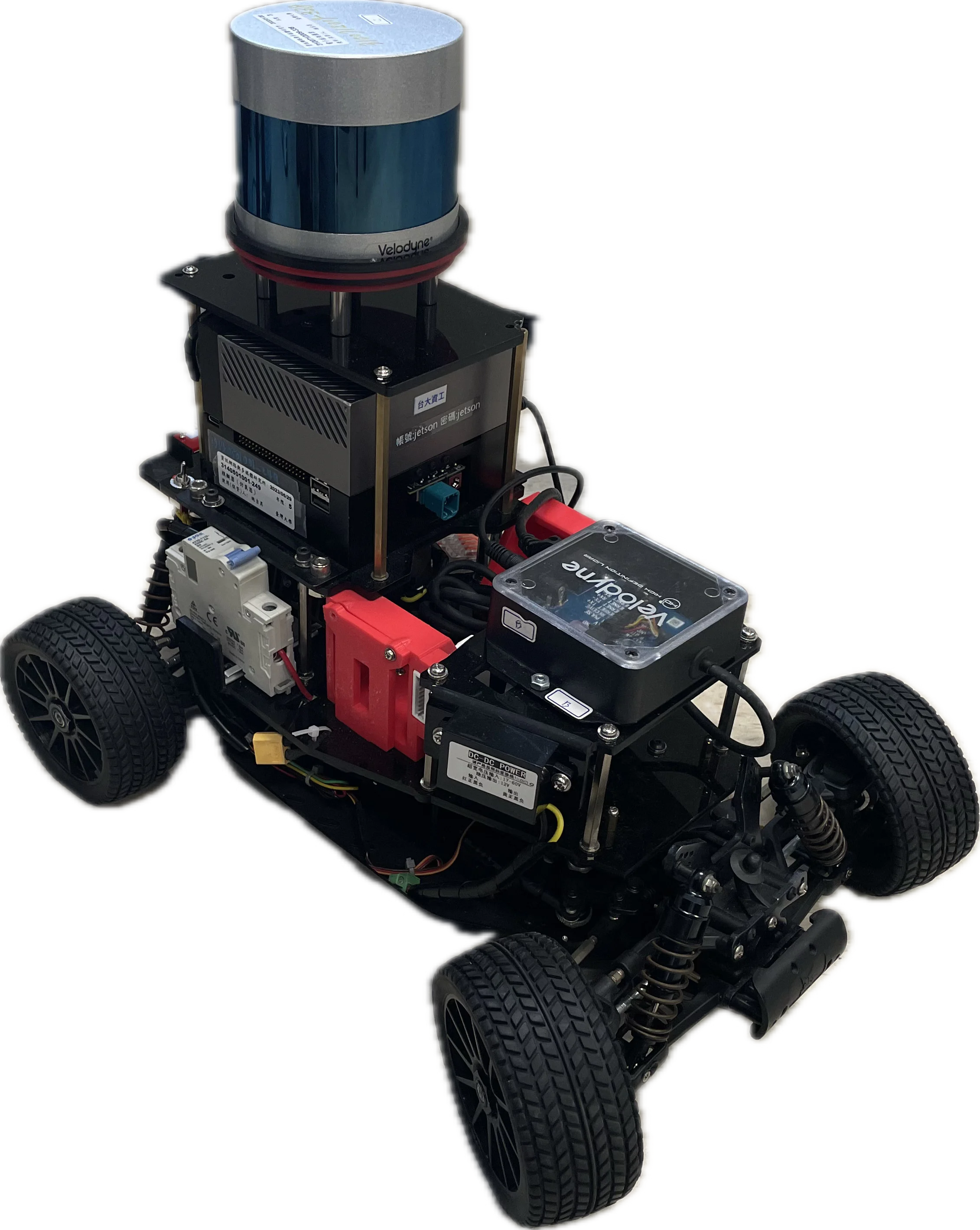
360° LiDAR Model

Production-ready configuration with proven Autoware integration. Features full NDT localization support.
Additional Components
| Component | Specification |
|---|---|
| LiDAR | Velodyne VLP-32C |
| LiDAR Mount | Top center bracket |
LiDAR Specifications
- Field of View: 360° × 40°
- Range: 100m
- Points/Second: 600,000
- Channels: 32
- Connection: Ethernet
Solid-State Model

Modern solid-state LiDAR platform with high point density. Localization features require development.
Additional Components
| Component | Specification |
|---|---|
| LiDAR | Seyond Robin-W |
| LiDAR Mount | Front-facing bracket |
LiDAR Specifications
- Field of View: 120° × 25°
- Range: 150m
- Points/Second: 750,000
- Technology: Solid-state (no moving parts)
- Connection: Ethernet
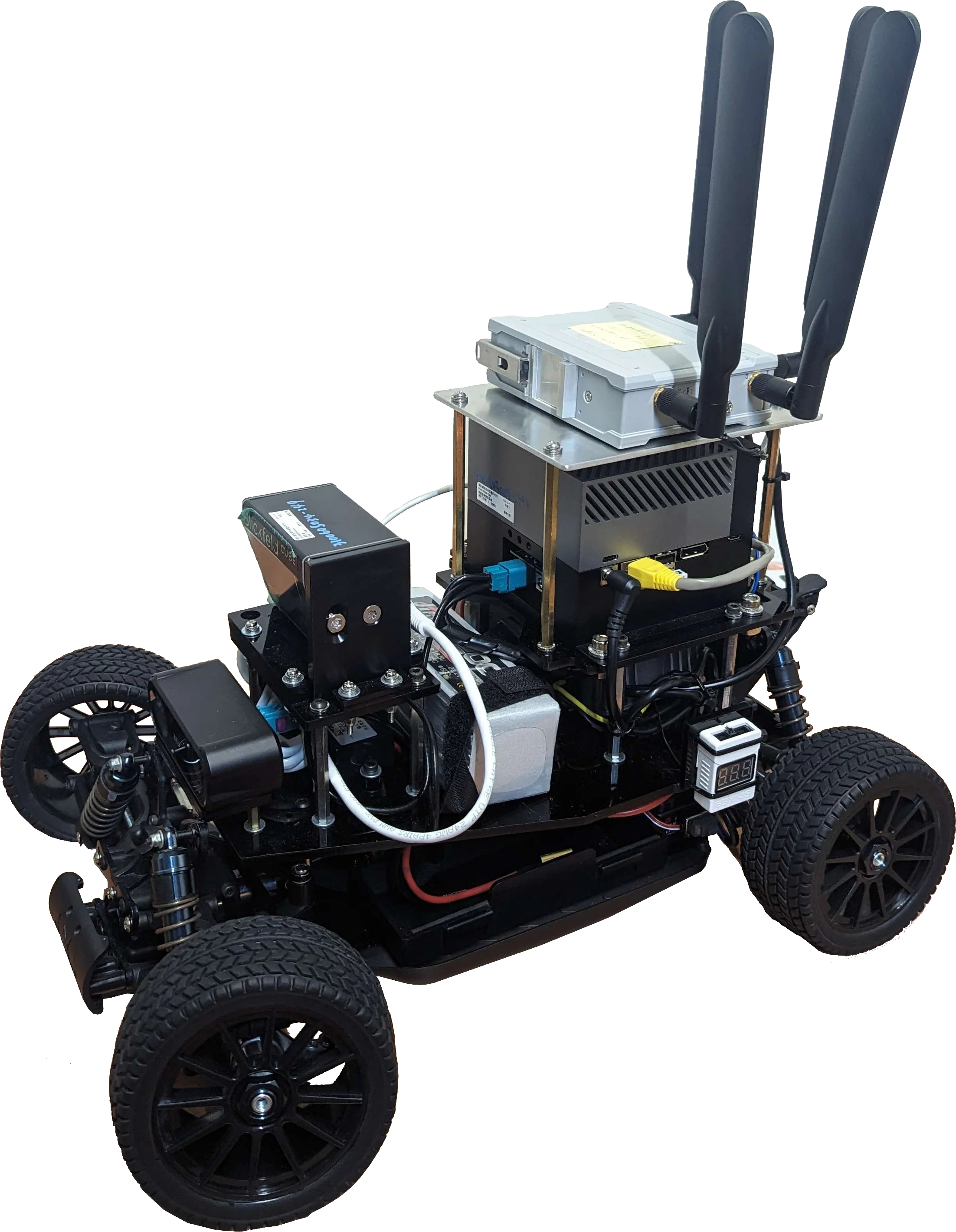
Connected Model

Connected platform enabling remote operation and fleet management. Note: 5G module occupies top mount position.
Additional Components
| Component | Specification |
|---|---|
| LiDAR | Seyond Robin-W |
| 5G Module | MOXA OnCell G4302 |
| LiDAR Mount | Front bracket |
| 5G Mount | Top center bracket |
LiDAR Specifications
- Field of View: 120° × 25°
- Range: 150m
- Points/Second: 750,000
- Technology: Solid-state (no moving parts)
- Connection: Ethernet
5G Specifications
Note: The MOXA OnCell G4302 is shown as an example 5G gateway. The actual 5G module selection is vendor-specific and can be customized based on deployment requirements.
- Network: 5G/LTE with fallback
- SIM Slots: Dual SIM for carrier redundancy
- Features: Remote operation, telemetry streaming, OTA updates
System Specifications
- Weight: 11.3 kg (33% heavier due to 5G kit)
- Battery Life: 40 minutes (upper), 2+ hours (lower)
- Connectivity: Requires 5G/LTE data plan
Next Steps
- Hardware Assembly Guide - Build instructions
- Software Installation - Software setup
Getting Started
This section guides you through the process of setting up and using the AutoSDV platform. Follow these chapters sequentially to build a fully functional autonomous vehicle:
Overview
- Building the Vehicle - Assembling the physical components and hardware
- Software Installation - Installing AutoSDV software using recommended methods
- Docker Setup - Alternative containerized installation
- Manual Setup - Advanced customization options
- Operating the Vehicle - Launching and controlling the system
Quick Start Paths
For Vehicle Deployment
Follow the chapters in order: Build → Install → Operate
For Simulation/Development
Skip to Software Installation or use Docker Setup for quick testing
For Customization
See Manual Setup and Customization for advanced configuration options
Building the Vehicle
The recommended vehicle build is based on a 16×11×5 inch chassis plus additional sensor and communication mounts, which can be divided into several parts listed below.
The core components include the necessary components to run Autoware.
- Onboard computer
- Navigation system
- Power supply system
- Powertrain system
- Chassis
The vehicle can be equipped with additional mounts depending on your choice.
- LiDAR sensors
- 5G/LTE communication module
Core Components
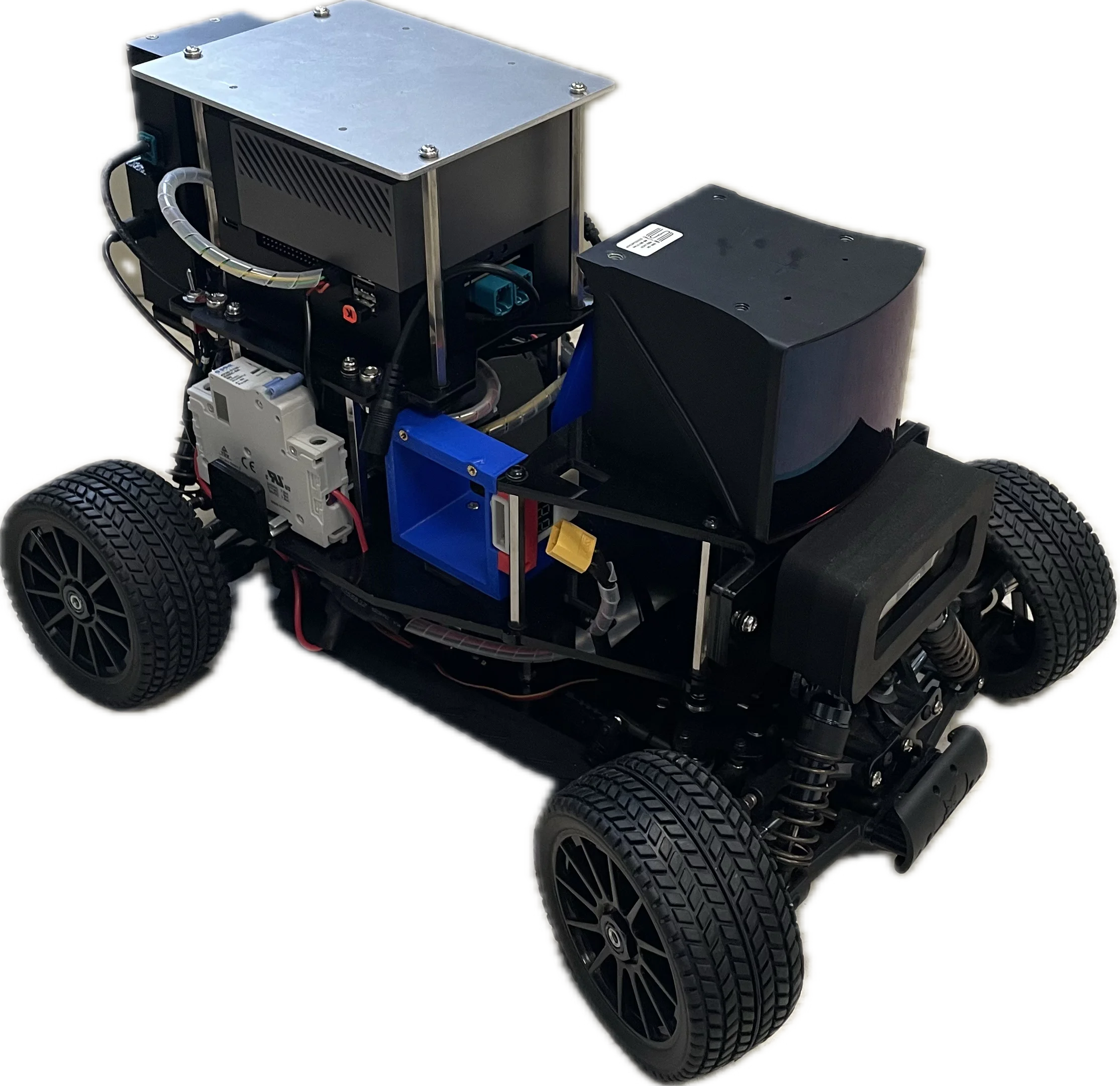
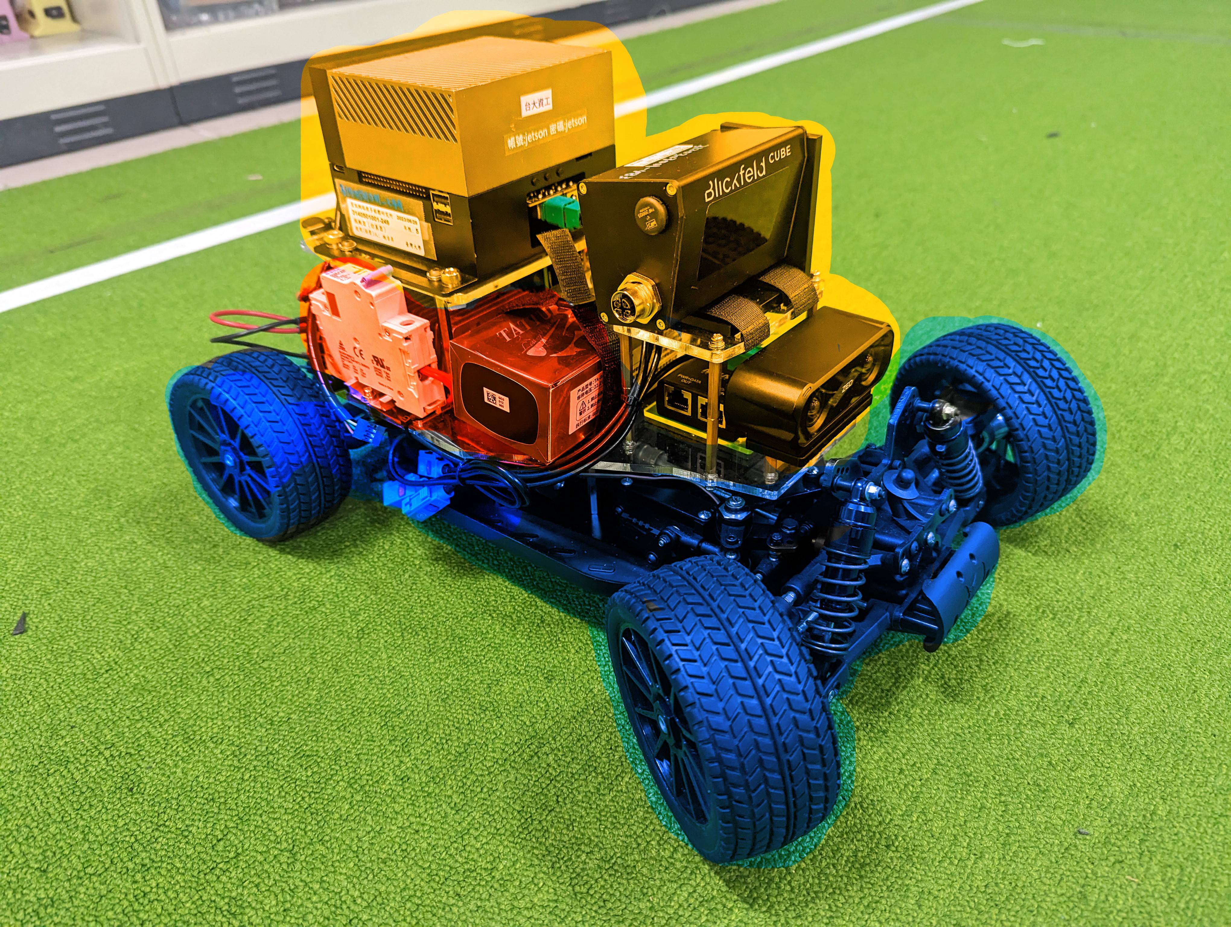
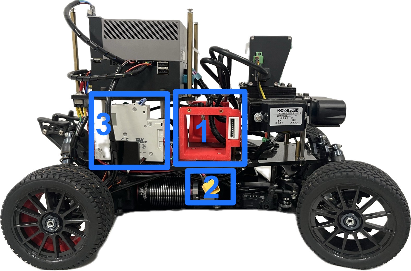
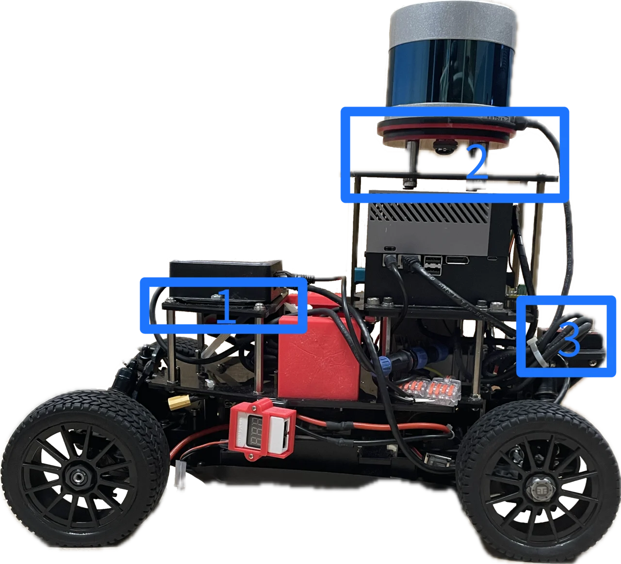
The vehicle has three major layers shown in the Figure 1 from top to bottom.
- Yellow: The onboard computer, navigation sensors and additional mounts.
- Red: Power supply system for the onboard computer and sensors in the yellow layer.
- Blue: Powertrain system and power supply for the powertrain.
By using this vehicle, additional sensors and 5G mounts go to the yellow layer, which power supply comes from the red layer. The motors have a separate battery and power supply in the blue layer due to distinct voltage requirements.
Power Supply System
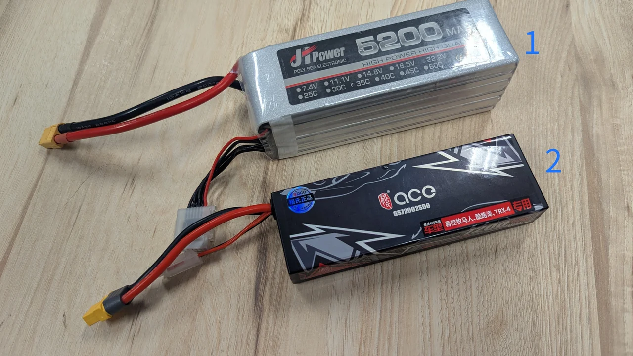
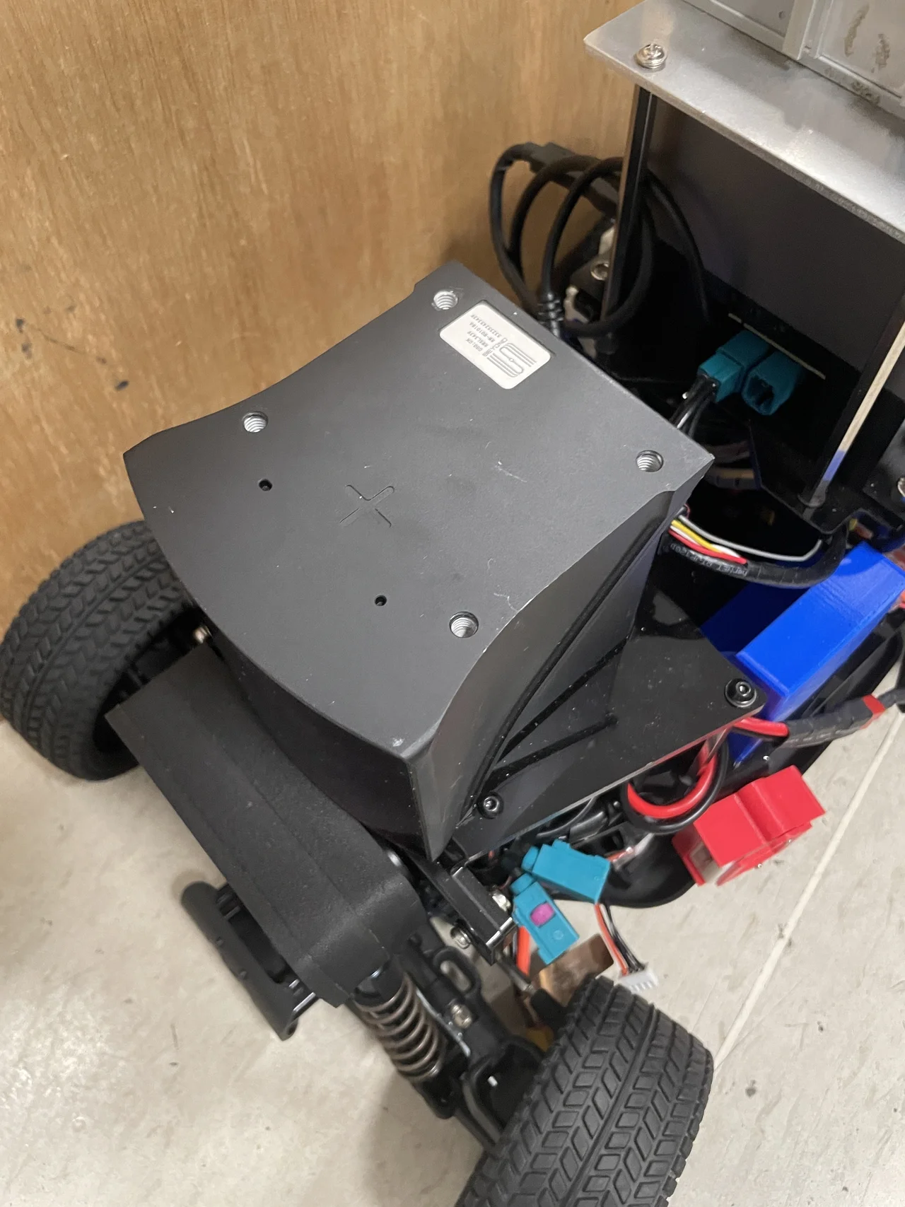
Batteries
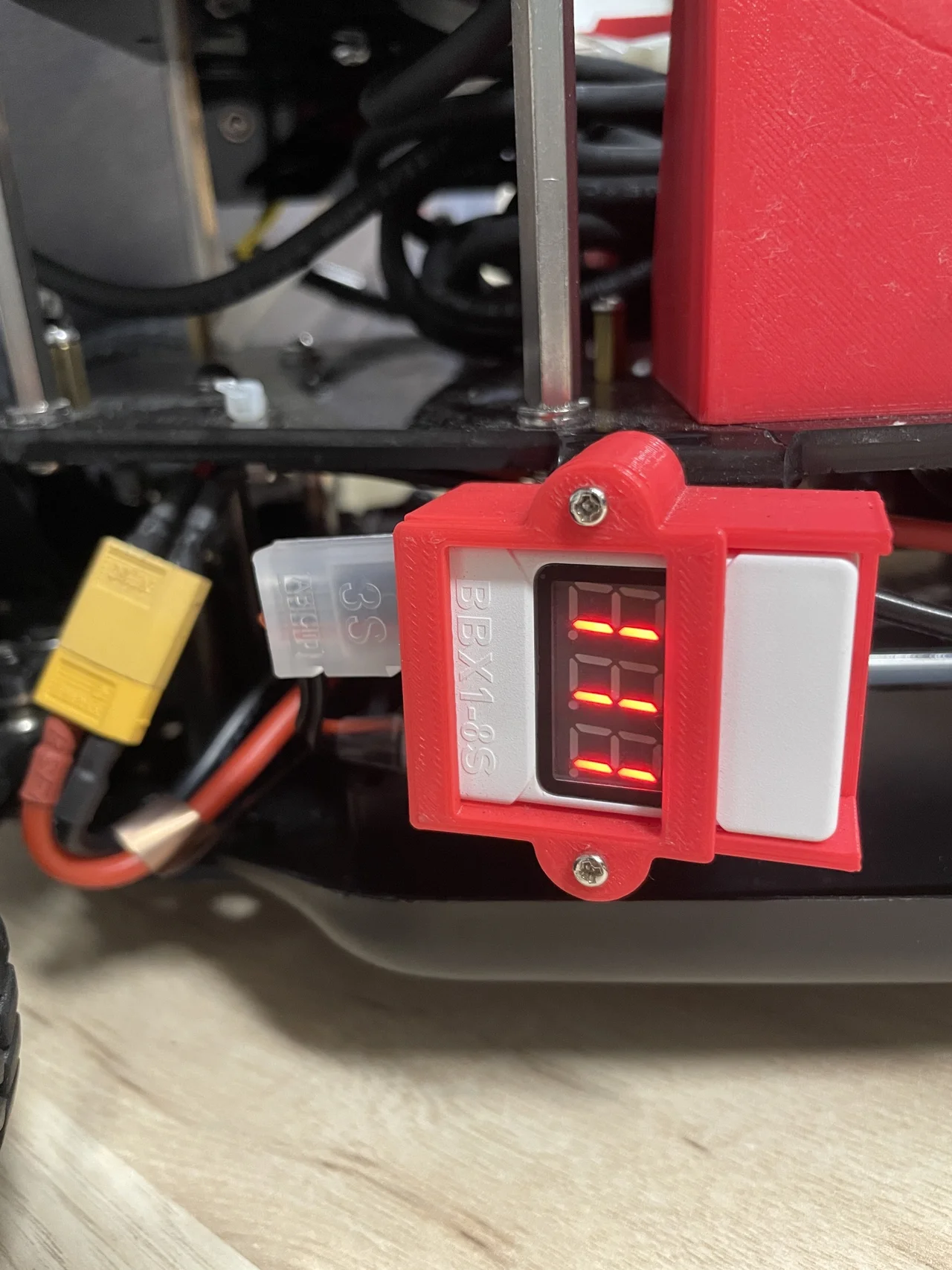
There are two batteries for the respective two power supplies, namely the upper power and lower power. The batteries are shown in Figure 2. The upper power provides electricity to the on-board computer and sensors from a 22.2V 6S battery (1), while the lower power provides electricity to the DC motor and powertrain from a 7.4V 2S battery (2).
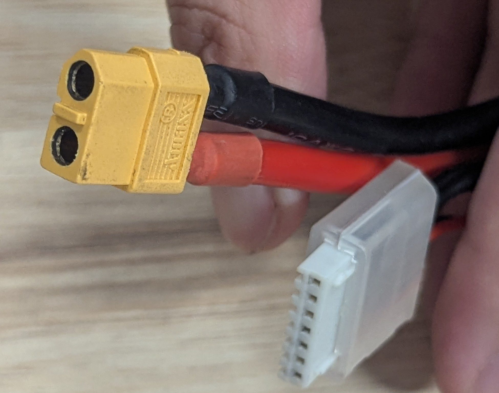
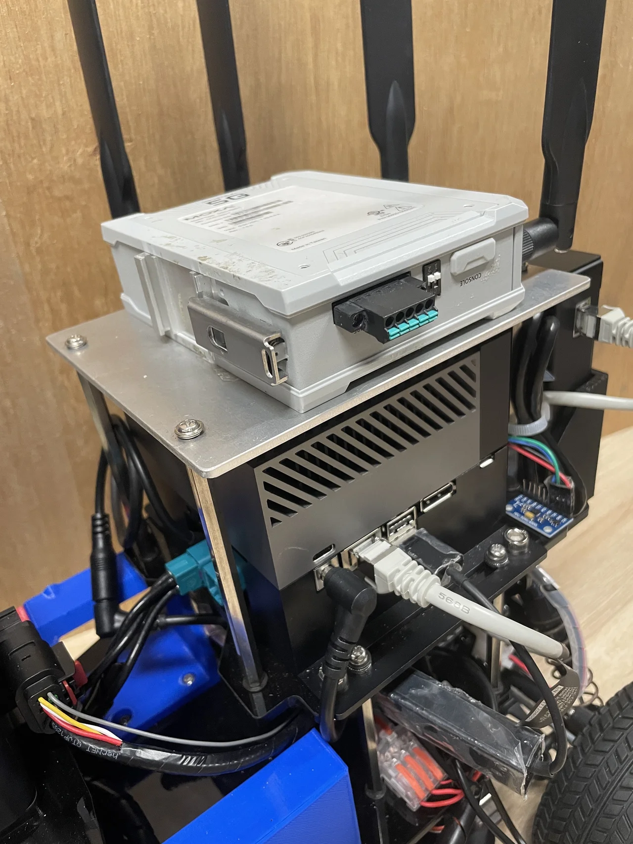
Both batteries have a yellow XT60 power plug and a white JST-XH connector as shown in Figure 3. The JST-XH connector is plugged to a voltage monitor in Figure 4. It beeps when the voltage becomes low.
The Upper Power Supply
The upper power start up process is shown in Figure 4. First, install the battery on the battery dock. Second, connect battery to the cable. Last, switch on the power supply demonstrated in Figure 5.
Please be cautious that the power switch must be turned off before installing or removing the battery. It's necessary to protect the system from voltage spikes.
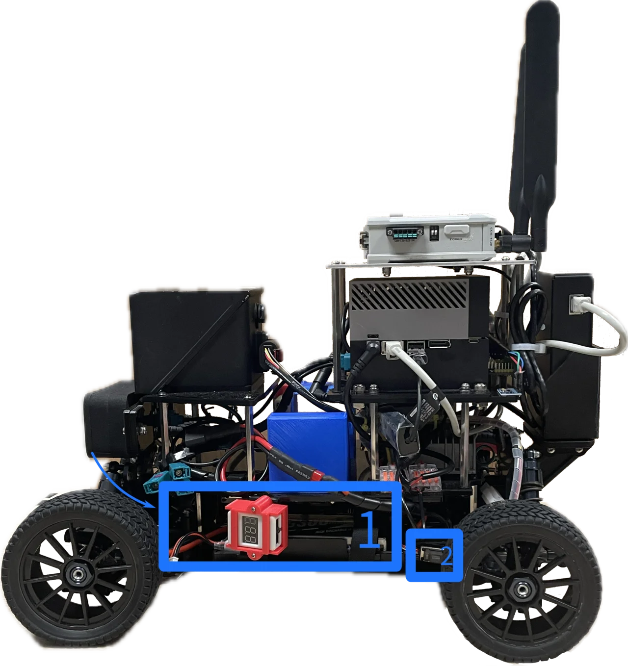
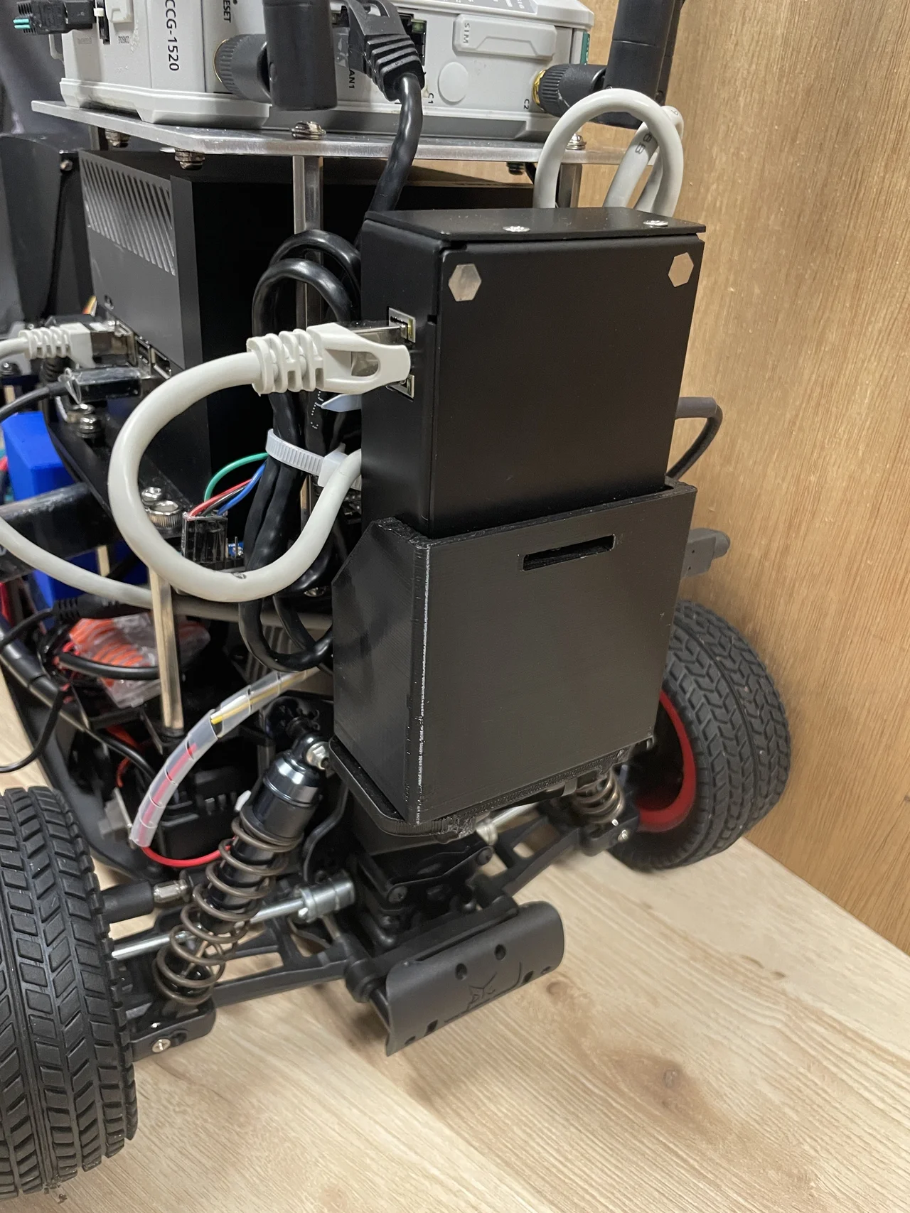
The Lower Power Supply
The lower power start up process is shown in Figure 6. The battery is installed in the dock in the bottom layer of the vehicle (1). Then, switch on the power (2).
Docks
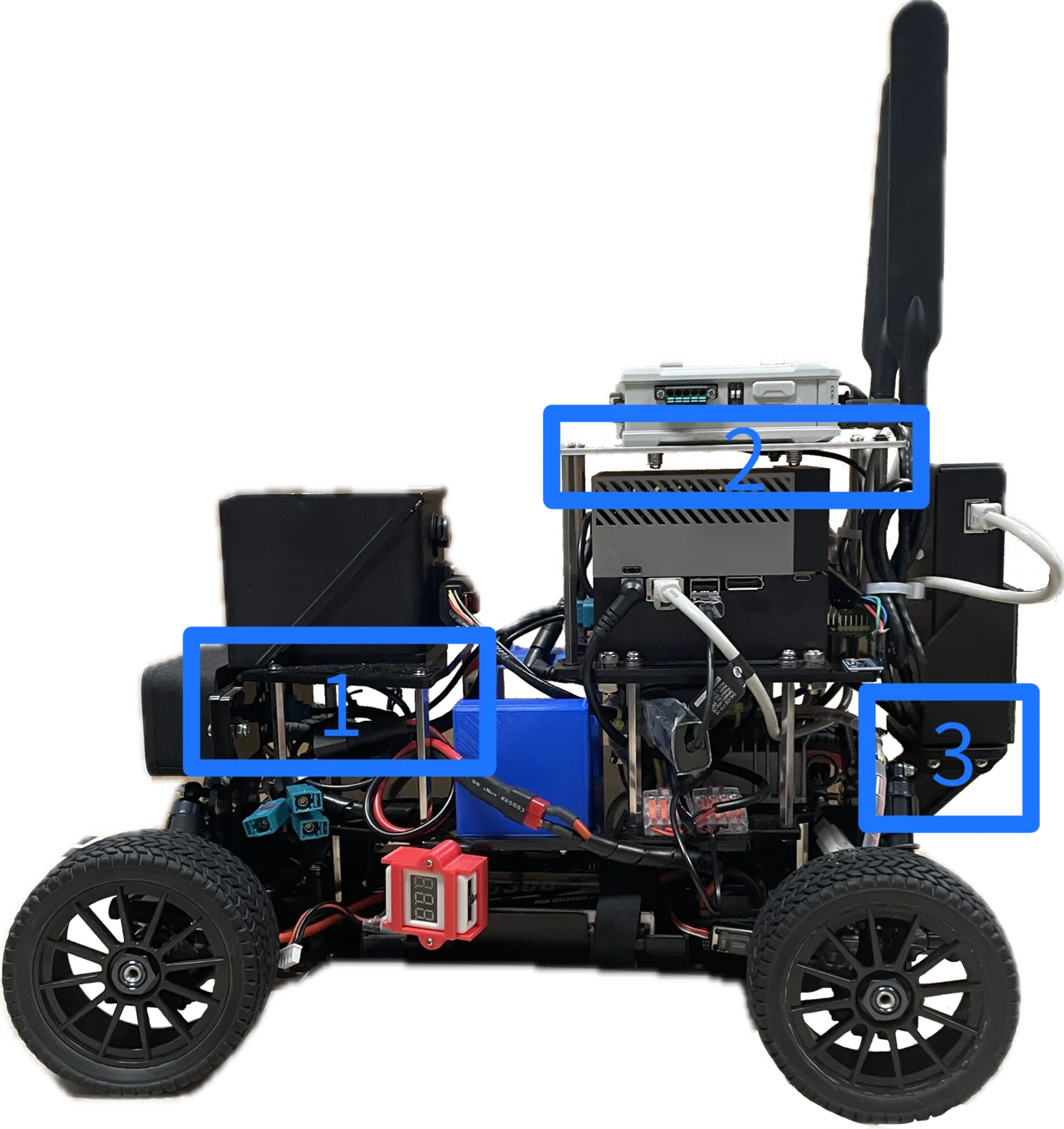
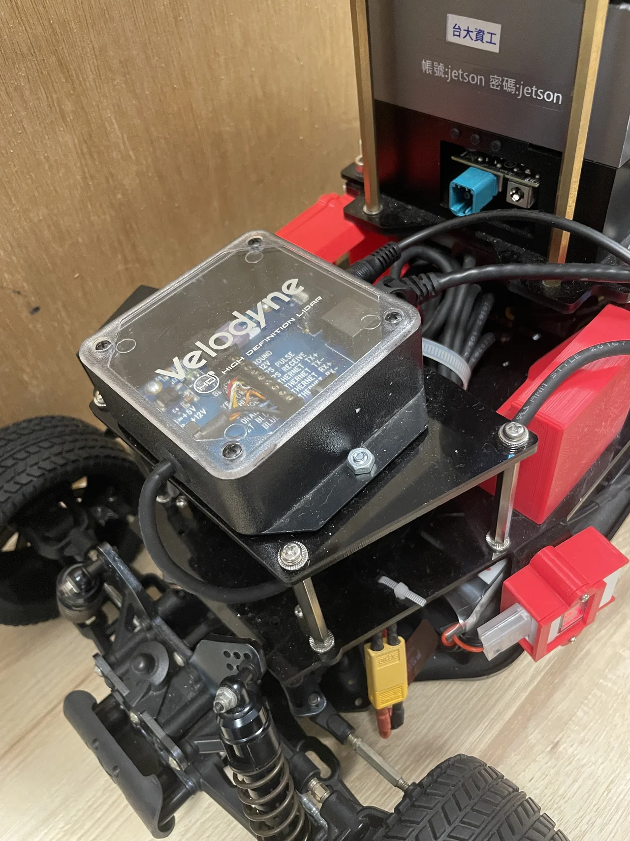
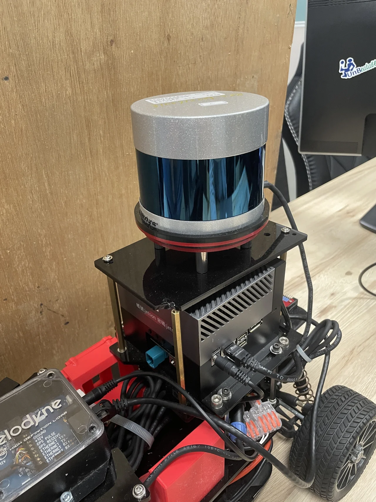
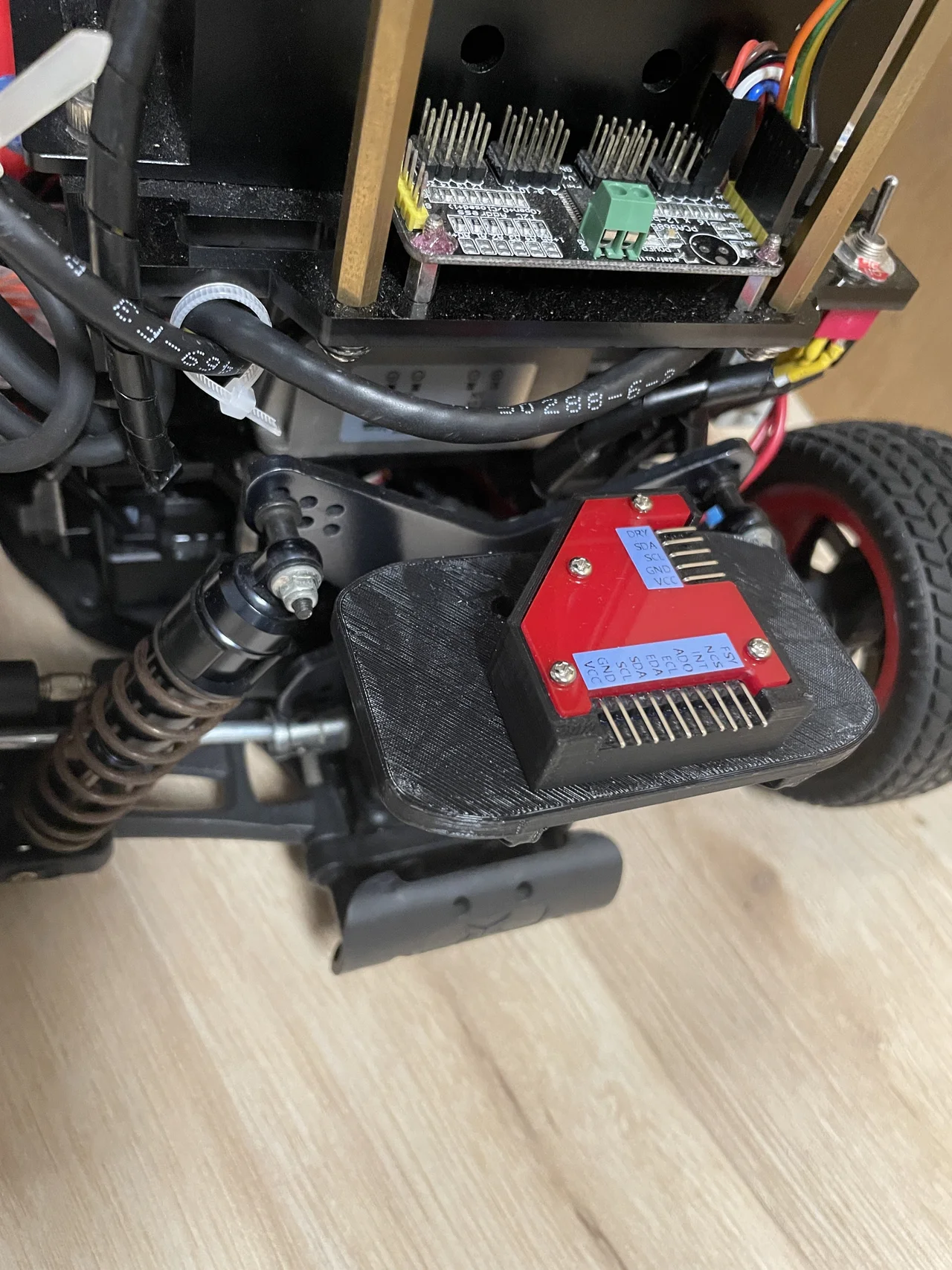
The vehicle has three docks to mount your favorite sensors. The figure below shows two kinds of builds with three docks marked on the figure: (1) the front dock, (2) the top dock and (3) the rear dock.
|
|
The details of two builds are described in the table below.
| No. | Front Dock | Top Dock | Rear Dock |
|---|---|---|---|
| 1 |
|
|
|
| Seyond Robin-W LiDAR | MOXA 5G Module | LiDAR Ethernet Adaptor | |
| 2 |
|
|
|
| Velodyne LiDAR Adaptor | Velodyne 32C LiDAR | Navigation Sensor Kit |
Components and Wiring
The vehicle incorporates essential components such as the chassis, body, onboard computer, among others, along with additional LiDARs and a 5G communication module. For detailed information on these elements and their wiring, please refer to the comprehensive guide in Hardware and Wiring.
Software Installation
This guide provides the recommended installation process for AutoSDV. For manual installation or customization options, see the Manual Setup Guide.
System Requirements
Hardware Options
Choose one of the following platforms:
- NVIDIA Jetson AGX Orin 64GB (Recommended for vehicle deployment)
- Ubuntu 22.04 PC with NVIDIA GPU (For development and testing)
- Docker Environment (For simulation and development) - See Docker Setup
Storage Requirements
- Minimum 256GB SSD (NVMe recommended for Jetson)
- At least 100GB free space for software installation
Installation Steps
Step 1: Prepare the Operating System
For NVIDIA Jetson AGX Orin
- Download and install NVIDIA SDK Manager
- Flash the Jetson with the following configuration:
- JetPack SDK version: 6.0 (exactly - not 6.1 or 6.2)
- Install all CUDA and TensorRT packages
- Flash to external NVMe SSD (not internal eMMC)
For Ubuntu 22.04 PC
- Install Ubuntu 22.04 LTS
- Install NVIDIA drivers (version 550 or higher):
sudo apt update sudo apt install nvidia-driver-550 - Install CUDA 12.3 using the deb (network) installer
- Install TensorRT 8.6 GA
Step 2: Clone AutoSDV Repository
cd ~
git clone https://github.com/NEWSLabNTU/AutoSDV.git
cd AutoSDV
Step 3: Run Automated Setup
The project includes an Ansible playbook that automatically configures your environment:
make setup
This script will:
- Install ROS 2 Humble
- Install Autoware 2025.02 binary release
- Install Blickfeld Scanner Library for Cube 1 LiDAR
- Download required Autoware artifacts
- Configure Cyclone DDS as default RMW
- Optimize system settings for real-time performance
Step 4: Install Additional Sensor Drivers
Some sensor drivers require manual installation:
ZED Camera SDK
- Visit the ZED SDK 4.2 Release Page
- Download and install:
- For Jetson AGX Orin: ZED SDK for JetPack 6.0 GA
- For Ubuntu 22.04 PC: ZED SDK for Ubuntu 22
# After downloading the installer
chmod +x ZED_SDK_*.run
sudo ./ZED_SDK_*.run
Seyond Robin-W LiDAR Driver (Optional)
If using the Robin-W LiDAR, install the Innovusion ROS driver:
- Contact Seyond/Innovusion to obtain the driver package
- Install the provided
.debpackage
Step 5: Build AutoSDV
cd ~/AutoSDV
make prepare  # Install ROS dependencies
make build    # Build the project
Step 6: Verify Installation
Test the installation by launching the system:
source install/setup.bash
ros2 launch autosdv_launch autosdv.launch.yaml
Next Steps
- Operating the Vehicle - Learn how to run AutoSDV
- Development Guide - Start developing with AutoSDV
- Docker Setup - Alternative Docker-based installation
- Manual Setup Guide - Manual installation and customization options
Troubleshooting
Build Errors with Autoware Dependencies
If you encounter missing Autoware package errors during build:
-
Ensure Autoware is properly installed:
source /opt/autoware/autoware-env -
Use the clean build script:
./clean_build.sh clean
CUDA/TensorRT Issues
Verify CUDA installation:
nvcc --version  # Should show 12.3
nvidia-smi      # Should show driver 550+
ROS 2 Environment Issues
Always source ROS 2 before building:
source /opt/ros/humble/setup.bash
Docker Setup
Docker provides a containerized environment for running AutoSDV without modifying your host system. This is ideal for development, testing, and simulation scenarios.
Use Cases
Docker is recommended for:
- Development and Testing: Consistent environment across different machines
- Simulation: Running AutoSDV without physical hardware
- CI/CD: Automated testing and deployment
- Quick Evaluation: Try AutoSDV without full installation
Prerequisites
Host System Requirements
- Ubuntu 20.04 or 22.04 (other Linux distributions may work)
- NVIDIA GPU with driver 470+ (for GPU acceleration)
- At least 50GB free disk space
- 16GB+ RAM recommended
Software Requirements
-
Docker Engine (20.10 or newer):
# Install Docker curl -fsSL https://get.docker.com -o get-docker.sh sudo sh get-docker.sh # Add user to docker group sudo usermod -aG docker $USER # Log out and back in for group changes to take effect -
NVIDIA Container Toolkit (for GPU support):
# Add NVIDIA repository distribution=$(. /etc/os-release;echo $ID$VERSION_ID) curl -s -L https://nvidia.github.io/nvidia-docker/gpgkey | sudo apt-key add - curl -s -L https://nvidia.github.io/nvidia-docker/$distribution/nvidia-docker.list | \ sudo tee /etc/apt/sources.list.d/nvidia-docker.list # Install nvidia-container-toolkit sudo apt update sudo apt install nvidia-container-toolkit sudo systemctl restart docker -
Docker Compose (optional, for multi-container setups):
sudo apt install docker-compose
Quick Start
Step 1: Clone AutoSDV Repository
git clone -b 2025.02 --recursive https://github.com/NEWSLabNTU/AutoSDV.git
cd AutoSDV/docker
Step 2: Bootstrap Docker Environment
Set up cross-architecture support (required for ARM64 emulation on x86_64):
make bootstrap
Step 3: Build Docker Image
Build the AutoSDV Docker image:
make build
This creates an image with:
- Ubuntu 22.04 base with ROS 2 Humble
- Autoware 2025.02 pre-installed
- All AutoSDV dependencies
- CUDA and TensorRT support
- Sensor driver libraries (except proprietary ones)
Step 4: Run Container
Start an interactive container session:
make run
You'll enter a shell with AutoSDV ready to use at /home/developer/AutoSDV.
Docker Image Details
Image Architecture
The AutoSDV Docker image is built for ARM64 architecture to match the Jetson platform. On x86_64 hosts, QEMU provides transparent emulation.
Pre-installed Software
- ROS 2 Humble with desktop tools
- Autoware 2025.02 binary release
- CUDA 12.3 and TensorRT 8.6
- Cyclone DDS configured as default
- Development tools: git, vim, tmux, htop
Volume Mounts
The make run command automatically mounts:
/tmp/.X11-unixfor GUI applications- NVIDIA GPU devices for CUDA access
Advanced Usage
Custom Run Options
Run with additional volumes or ports:
docker run -it --rm \
  --gpus all \
  --network host \
  -v /path/to/data:/data \
  -v /dev:/dev \
  --privileged \
  autosdv:latest
Development Workflow
For active development, mount your local code:
docker run -it --rm \
  --gpus all \
  -v $(pwd):/workspace/AutoSDV \
  -w /workspace/AutoSDV \
  autosdv:latest
GUI Applications
Enable X11 forwarding for visualization tools:
xhost +local:docker
docker run -it --rm \
  --gpus all \
  -e DISPLAY=$DISPLAY \
  -v /tmp/.X11-unix:/tmp/.X11-unix \
  autosdv:latest
Then run GUI applications like RViz:
# Inside container
rviz2
Multi-Container Setup
Create a docker-compose.yml for complex deployments:
version: '3.8'

services:
  autosdv:
    image: autosdv:latest
    runtime: nvidia
    network_mode: host
    privileged: true
    volumes:
      - /dev:/dev
      - ./data:/data
    environment:
      - ROS_DOMAIN_ID=0
      - DISPLAY=${DISPLAY}
    command: ros2 launch autosdv_launch autosdv.launch.yaml

  monitoring:
    image: autosdv:latest
    runtime: nvidia
    network_mode: host
    environment:
      - ROS_DOMAIN_ID=0
    command: python3 /home/developer/AutoSDV/src/launcher/autosdv_launch/autosdv_launch/autosdv_monitor.py
Run with:
docker-compose up
Container Management
Save and Load Images
Export image for deployment:
make save # Creates autosdv_docker.tar.gz
Load on another machine:
docker load < autosdv_docker.tar.gz
Clean Up
Remove container and image:
make clean
Limitations
Hardware Access
Docker containers have limited hardware access:
- No direct LiDAR access (USB/Ethernet sensors need special configuration)
- No CAN bus without
--privilegedflag - Camera access requires device mounting
Performance
- ARM64 emulation on x86_64 reduces performance
- GPU passthrough adds overhead
- Network performance may vary with Docker networking modes
Sensor Drivers
Some proprietary sensor drivers cannot be included:
- ZED SDK (requires manual installation)
- Seyond Robin-W driver (vendor-specific)
Troubleshooting
GPU Not Accessible
Verify NVIDIA runtime:
docker run --rm --gpus all nvidia/cuda:11.8.0-base-ubuntu22.04 nvidia-smi
Network Issues
Use host networking for ROS 2 communication:
docker run --network host ...
Permission Denied
For device access, run with privileges:
docker run --privileged -v /dev:/dev ...
Build Failures
Clear Docker cache and rebuild:
docker system prune -a
make bootstrap
make build
Integration with CI/CD
GitHub Actions Example
name: AutoSDV Tests

on: [push, pull_request]

jobs:
  test:
    runs-on: ubuntu-latest
    steps:
      - uses: actions/checkout@v2

      - name: Set up Docker
        uses: docker/setup-buildx-action@v1

      - name: Build Docker image
        run: |
          cd docker
          make build

      - name: Run tests
        run: |
          docker run --rm autosdv:latest \
            bash -c "cd /home/developer/AutoSDV && colcon test"
Jenkins Pipeline Example
pipeline {
    agent any

    stages {
        stage('Build') {
            steps {
                sh 'cd docker && make build'
            }
        }

        stage('Test') {
            steps {
                sh 'docker run --rm autosdv:latest make test'
            }
        }
    }
}
Next Steps
- Software Installation - Native installation guide
- Usage Guide - Operating AutoSDV
- Development Guide - Development workflows
- Manual Setup - Customization options
Manual Setup and Customization
This guide provides detailed manual installation steps and customization options for advanced users. For the recommended automated installation, see the Software Installation guide.
Manual Environment Setup
ROS 2 Humble Installation
If you prefer to install ROS 2 manually instead of using the Ansible script:
-
Add ROS 2 apt repository:
sudo apt update && sudo apt install curl -y sudo curl -sSL https://raw.githubusercontent.com/ros/rosdistro/master/ros.key -o /usr/share/keyrings/ros-archive-keyring.gpg echo "deb [arch=$(dpkg --print-architecture) signed-by=/usr/share/keyrings/ros-archive-keyring.gpg] http://packages.ros.org/ros2/ubuntu $(. /etc/os-release && echo $UBUNTU_CODENAME) main" | sudo tee /etc/apt/sources.list.d/ros2.list > /dev/null -
Install ROS 2 Humble:
sudo apt update sudo apt install ros-humble-desktop ros-dev-tools -
Configure environment:
echo "source /opt/ros/humble/setup.bash" >> ~/.bashrc
source ~/.bashrc
Autoware Installation Options
Option 1: Build Autoware from Source
For developers who want to modify Autoware components:
-
Clone Autoware repository:
mkdir -p ~/autoware_ws cd ~/autoware_ws git clone https://github.com/autowarefoundation/autoware.git -b release/2025.02 -
Install dependencies:
cd autoware ./setup-dev-env.sh sudo apt install python3-vcstool -
Import repositories and build:
mkdir src vcs import src < autoware.repos rosdep install -y --from-paths src --ignore-src --rosdistro humble colcon build --symlink-install --cmake-args -DCMAKE_BUILD_TYPE=Release -
Source the workspace:
echo "source ~/autoware_ws/autoware/install/setup.bash" >> ~/.bashrc
Option 2: Custom Autoware Configuration
To use a custom Autoware installation path:
-
Modify the build script:
export AUTOWARE_PATH=/your/custom/autoware/path -
Update AutoSDV's build configuration: Edit
~/AutoSDV/clean_build.shand change the Autoware path:AUTOWARE_WS="/your/custom/autoware/path"
Manual Sensor Driver Installation
Blickfeld Scanner Library
Manual installation for different architectures:
-
Download the appropriate package:
- ARM64 (Jetson): blickfeld-scanner-lib_2.20.6-1_arm64.deb
- AMD64 (PC): blickfeld-scanner-lib_2.20.6-1_amd64.deb
-
Install the package:
sudo dpkg -i blickfeld-scanner-lib_*.deb
sudo apt-get install -f  # Fix any dependency issues
Velodyne LiDAR Driver
For Velodyne VLP-32C support:
sudo apt install ros-humble-velodyne ros-humble-velodyne-pointcloud
GNSS/IMU Drivers
Install additional GNSS and IMU support:
# NMEA GPS support
sudo apt install ros-humble-nmea-navsat-driver

# Serial communication for IMU
sudo apt install ros-humble-serial-driver
pip3 install pyserial
System Optimization
Real-time Performance Tuning
-
Configure CPU governor:
sudo apt install cpufrequtils echo 'GOVERNOR="performance"' | sudo tee /etc/default/cpufrequtils sudo systemctl restart cpufrequtils -
Increase system limits: Add to
/etc/security/limits.conf:* soft memlock unlimited * hard memlock unlimited * soft rtprio 99 * hard rtprio 99 -
Disable CPU frequency scaling (Jetson):
sudo jetson_clocks
sudo nvpmodel -m 0  # Maximum performance mode
Network Configuration
Configure Cyclone DDS
-
Create configuration file:
mkdir -p ~/.ros cat > ~/.ros/cyclone_dds.xml << EOF <?xml version="1.0" encoding="UTF-8" ?> <CycloneDDS xmlns="https://cdds.io/config" xmlns:xsi="http://www.w3.org/2001/XMLSchema-instance"> <Domain> <General> <NetworkInterfaceAddress>auto</NetworkInterfaceAddress> <AllowMulticast>true</AllowMulticast> </General> <Discovery> <ParticipantIndex>auto</ParticipantIndex> <MaxAutoParticipantIndex>120</MaxAutoParticipantIndex> </Discovery> </Domain> </CycloneDDS> EOF -
Set as default RMW:
echo "export RMW_IMPLEMENTATION=rmw_cyclonedds_cpp" >> ~/.bashrc
echo "export CYCLONEDDS_URI=file://$HOME/.ros/cyclone_dds.xml" >> ~/.bashrc
Configure FastDDS (Alternative)
If you prefer FastDDS over Cyclone DDS:
sudo apt install ros-humble-rmw-fastrtps-cpp
export RMW_IMPLEMENTATION=rmw_fastrtps_cpp
Custom Build Options
Debug Build
For development with debug symbols:
cd ~/AutoSDV
colcon build \
  --base-paths src \
  --symlink-install \
  --cmake-args -DCMAKE_BUILD_TYPE=Debug
Selective Package Building
Build only specific packages:
# Build only vehicle interface packages
colcon build --packages-select \
  autosdv_vehicle_interface \
  autosdv_vehicle_launch

# Build with dependencies
colcon build --packages-up-to autosdv_launch
Cross-compilation
For cross-compiling to different architectures:
# Example for ARM64 on x86_64 host
colcon build \
  --cmake-args \
  -DCMAKE_TOOLCHAIN_FILE=/path/to/toolchain.cmake \
  -DCMAKE_BUILD_TYPE=Release
Environment Variables
Essential Variables
Add to ~/.bashrc for persistent configuration:
# ROS 2 Configuration
export ROS_DOMAIN_ID=0  # Change for multi-robot setups
export ROS_LOCALHOST_ONLY=0  # Set to 1 for local-only communication

# GPU Configuration (if applicable)
export CUDA_HOME=/usr/local/cuda
export PATH=$CUDA_HOME/bin:$PATH
export LD_LIBRARY_PATH=$CUDA_HOME/lib64:$LD_LIBRARY_PATH

# Autoware Configuration
export AUTOWARE_PATH=/opt/autoware  # Or your custom path
Development Tools
Install additional development utilities:
# Code formatting and linting
sudo apt install clang-format python3-autopep8

# Debugging tools
sudo apt install gdb valgrind ros-humble-plotjuggler

# Build acceleration
sudo apt install ccache
export CC="ccache gcc"
export CXX="ccache g++"
Troubleshooting Manual Installations
Missing Dependencies
If encountering missing package errors:
# Update rosdep database
rosdep update

# Install missing dependencies
cd ~/AutoSDV
rosdep install --from-paths src --ignore-src -r -y
Library Path Issues
For custom library installations:
# Add custom library paths
echo "/usr/local/lib" | sudo tee /etc/ld.so.conf.d/local.conf
sudo ldconfig
Permission Issues
For device access (sensors, CAN bus):
# Add user to required groups
sudo usermod -a -G dialout $USER
sudo usermod -a -G plugdev $USER
# Logout and login for changes to take effect
Next Steps
- Return to Software Installation for the standard setup
- See Docker Setup for containerized deployment
- Continue to Development Guide for development workflows
Operating the Vehicle
Before reading this article, please make sure you followed the Software Installation and built the project. The project repository has a launch file autosdv.launch.yaml that defines the set of nodes to be executed and assigned parameters to start the whole driving system.
The Simple Way
The Makefile has a receipt to start the whole system.
make launch
Customize the Launch
You can either modify the launch file directly located here:
AutoSDV/src/autoware/launcher/autosdv_launch/launch/autosdv.launch.yaml
or assign argument values to the launch command. For example, to set launch_sensing_driver to false.
source install/setup.bash
ros2 launch autosdv_launch autosdv.launch.yaml launch_sensing_driver:=false
Arguments
| Argument | Value | Default |
|---|---|---|
vehicle_model | The name of the vehicle model. | autosdv_vehicle |
sensor_model | The name of the sensor model. | autosdv_sensor_kit |
map_path | The path to the map data directory. | ./data/COSS-map-planning |
launch_vehicle | Whether to launch the vehicle interface. | true |
launch_system | Whether to launch the system component. | false |
launch_map | Whether to launch the map component. | false |
launch_sensing | Whether to launch the sensing component. | true |
launch_sensing_driver | Whether to launch sensor drivers. | true |
launch_localization | Whether to launch the localization component. | false |
launch_perception | Whether to launch the perception component. | false |
launch_planning | Whether to launch the planning component. | false |
launch_control | Whether to launch the control component. | true |
pose_source | The localization method. | eagleye |
Development Guide
This section provides information for developers who want to extend, modify, or contribute to the AutoSDV platform. The guide covers five key areas:
- Source Code Walkthrough - Repository structure and organization
- Version Control - Working with Git superproject and submodules
- Sensor Components and Drivers - Available sensors and their configuration
- Sensor Kit Configuration - Sensor integration and calibration
- Vehicle Interface - Control systems and vehicle parameters
Source Code Walkthrough
The AutoSDV follows the superproject convention. It collects hundreds of packages as Git submodules classified by their functions into directories. It is built atop Autoware plus additional packages specific to the project and constitutes a large ROS workspace.
Here you can visit the GitHub repository:
https://github.com/NEWSLabNTU/AutoSDV.
| Directory | Function |
|---|---|
AutoSDV/ | |
├── book/ | The source documents for this book. |
├── data/ | It includes data files used or loaded in the runtime. |
├── docker/ | The Docker container build script. |
├── scripts/ | Auxiliary script files. It contains Ansible scripts to set up the environment. |
├── src/ | The source code packages. |
├── Makefile | It includes commonly used recipes. |
└── README.md | The introductory document to get the first impression of the project. |
Source Package Categories
| Directory | Function |
|---|---|
AutoSDV/src/ | The entry to the Autoware source tree. |
├── core/ | The Autoware.Core library. |
├── launcher/ | Includes launch files to run the entire driving system. |
├── vehicle/ | Powertrain control and kinetic parameters. |
├── param/ | Parameters specific to vehicle models. |
├── sensor_component/ | Sensor drivers and sensing data processors. |
└── sensor_kit/ | Sensor related parameters and launch files. |
Vehicle Interface Packages
AutoSDV/src/vehicle/autosdv_vehicle_launch/
| Directory | Function |
|---|---|
.../autosdv_vehicle_launch/ | |
├── autosdv_vehicle_interface/ | Powertrain control and its state measurement. |
├── autosdv_vehicle_description/ | Vehicle shape parameters and mesh files. |
└── autosdv_vehicle_launch/ | Launch files to start the vehicle interface. |
The Package for Vehicle-Specific Parameters
The autoware_individual_params package serves parameters that are specific to different vehicle models. It is located at
AutoSDV/src/param/autoware_individual_params
You can find the parameter directories within this package.
.../autoware_individual_params/individual_params/default/
| Directory | Function |
|---|---|
.../default/ | |
├── awsim_sensor_kit | Parameters for the AWSIM vehicle. |
└── autosdv_sensor_kit | Parameters for the AutoSDV vehicle. |
├── imu_corrector.param.yaml | |
├── sensor_kit_calibration.yaml | |
└── sensors_calibration.yaml |
Sensor Related Packages
| Directory | Function |
|---|---|
AutoSDV/src/ | |
├── sensor_component/ | Sensor drivers and preprocessors. |
└── sensor_kit/ | |
└── autosdv_sensor_kit_launch/ | |
├── autosdv_sensor_kit_description/ | Coordinates of each sensor. |
└── autosdv_sensor_kit_launch/ | Additional launch files for sensors. |
Version Control
The project adopts the superproject approach to manage a large number of Git repositories. The AutoSDV repository itself, the said superproject, saves the sub-projects as Git submodules but does not store their actual data. You can learn from the tutorial here to get the impression of superproject.
A Git submodule works as though it is a hyperlink within the mother repository. The mother repository stores information about submodules in the .gitmodules file. You can list them by:
git submodule status
Notice
The official Autoware adopts a different version control strategy from ours. Do not confuse them.
Download a Repository with Submodules
Always add the --recursive option when downloading a repository containing submodules.
git clone --recursive https://github.com/NEWSLabNTU/AutoSDV.git
If you forget to add the option, the submodule directories will be empty. You can get the submodule contents afterwards.
cd AutoSDV/
git submodule update --init --recursive
Inspect a Submodule
Let's check the src/autoware/core/autoware.core submodule for example. Open the .gitmodules and you can see the section below. It tells the directory location to the submodule and also the upstream URL.
[submodule "src/autoware/core/autoware.core"]
        path = src/autoware/core/autoware.core
        url = https://github.com/autowarefoundation/autoware.core.git
The path src/autoware/core/autoware.core is treated as a link file in the viewpoint of the mother repo. It stores the commit hash to the tracked Git repository. You can show the commit hash the command below. If the commit hash changes, we go through the usual git add & commit to save it.
$ git submodule status src/autoware/core/autoware.core
 99891401473b5740e640f5a0cc0412c0984b8e0b src/autoware/core/autoware.core (v1.0~1)
Save Changes within a Submodule
To save the changes within a submodule, you must commit the changes both in the submodule repo and in the mother repo in a two-step fashion.
Let's see src/autoware/sensor_kit/autosdv_sensor_kit_launch submodule for example.
| Committed Changes | Pushed to Upstream Repository |
|---|---|
Changes within the autosdv_sensor_kit_launch submodule. | autosdv_sensor_kit_launch subproject repository |
New commit hash on the autosdv_sensor_kit_launch submodule | AutoSDV mother repository |
The walk through goes like this.
# Go into the submodule and check to the branch we want to work on.
cd src/autoware/sensor_kit/autosdv_sensor_kit_launch
git checkout main

# Do some work in the submodule.
touch a_new_file  # Create a file

# Commit and push to the upstream repo.
git add a_new_file
git commit -m 'Add a new file'
git push

# Go back to the mother repo
cd -

# Save the new commit hash on the submodule and push it to the upstream repo.
git add src/autoware/core/autoware.core
git commit -m 'Update the autoware.core submodule'
git push
Technical Reference
This section provides detailed technical specifications, wiring diagrams, and component details for the AutoSDV platform. This information supplements the model-specific guides with in-depth technical documentation.
Contents
Core Components
- Core Components Specification - Detailed specifications for all base platform components
- Wiring Diagrams - Electrical connections and power distribution
Advanced Topics
- 5G/LTE Deployment - Detailed guide for cellular connectivity setup
- Sensor Components and Drivers - Low-level sensor integration
- Sensor Kit Configuration - ROS 2 sensor configuration details
- Vehicle Interface - CAN bus and actuator control
Quick Reference Tables
Power Requirements
| Component | Voltage | Current (Typical) | Current (Peak) |
|---|---|---|---|
| Jetson AGX Orin | 9-20V | 2.5A @ 12V | 4A @ 12V |
| Velodyne VLP-32C | 9-32V | 1A @ 12V | 1.5A @ 12V |
| Robin-W LiDAR | 12-24V | 0.7A @ 12V | 1A @ 12V |
| Cube1 LiDAR | 12-24V | 0.7A @ 12V | 1A @ 12V |
| ZED X Mini | 12V | 0.5A | 0.8A |
| 5G Module | 12V | 1.2A | 2A |
Communication Interfaces
| Interface | Purpose | Protocol | Bandwidth |
|---|---|---|---|
| Ethernet (GbE) | LiDAR data | UDP | 1 Gbps |
| USB 3.0 | Camera data | USB | 5 Gbps |
| CAN Bus | Vehicle control | CAN 2.0B | 1 Mbps |
| I2C | Sensors | I2C | 400 kbps |
| UART | GPS/IMU | Serial | 115200 baud |
Environmental Specifications
| Parameter | Operating Range | Storage Range |
|---|---|---|
| Temperature | -10°C to +50°C | -20°C to +60°C |
| Humidity | 10% to 90% RH | 5% to 95% RH |
| Vibration | 2G RMS | 5G RMS |
| Shock | 15G peak | 30G peak |
| Ingress Protection | IP54 (with enclosure) | - |
System Architecture
Data Flow
Sensors → Processing → Decision → Control → Actuators
   ↓          ↓           ↓         ↓          ↓
LiDAR    Perception   Planning   Commands   Motors
Camera   Localization  Safety    Validation  Steering
IMU/GPS  Fusion        Behavior  Monitoring  Brakes
Software Stack
Application Layer:     User Applications
     ↓
Autoware Layer:       Perception, Planning, Control
     ↓
ROS 2 Middleware:     DDS Communication
     ↓
Driver Layer:         Sensor/Actuator Drivers
     ↓
OS Layer:            Ubuntu 22.04 + RT Kernel
     ↓
Hardware Layer:       Jetson AGX Orin
Maintenance Schedule
Daily Checks
- Visual inspection of components
- Battery voltage check
- Sensor lens cleaning
Weekly Maintenance
- Connector inspection
- Wheel bearing check
- Software updates
Monthly Service
- Full system diagnostic
- Calibration verification
- Performance benchmarking
Annual Overhaul
- Complete disassembly and inspection
- Bearing replacement (if mechanical LiDAR)
- Sensor recalibration
- Structural integrity check
Troubleshooting Quick Reference
Common Issues
| Symptom | Likely Cause | Solution |
|---|---|---|
| No LiDAR data | Network config | Check IP settings |
| Poor localization | Map mismatch | Regenerate map |
| Erratic motion | IMU calibration | Recalibrate IMU |
| Short battery life | High load | Check CPU usage |
| Communication loss | Interference | Check wireless channels |
Safety Specifications
Emergency Stop
- Hardware E-stop button
- Software emergency brake
- Remote kill switch (5G model)
- Automatic fault detection
Operating Limits
- Maximum speed: 15 km/h
- Maximum payload: 5 kg
- Maximum incline: 15°
- Minimum lighting: 10 lux (with lights)
Compliance & Certification
Standards
- ROS 2: REP-2000 compliant
- Safety: ISO 26262 ASIL-B capable
- EMC: FCC Part 15 Class B
- Environmental: MIL-STD-810G tested
Documentation
- Full schematics available
- Open-source software
- Hardware design files
- Test reports
Additional Resources
- Hardware Assembly Guide - Step-by-step assembly
- Software Installation - Software setup
- Development Guide - Custom development
Hardware Components and Wiring
Hardware Components
The vehicle is assembled using core components and optional supplementary components. The core components include the chassis and other essential parts. Supplementary components, such as the LiDAR and 5G/LTE module, are optional and can be selected based on your specific requirements.
Core Components
| Items |
|---|
| # Chassis |
| Tekno TKR9500 Truck Kit 16×11×5 inch |
| ⎯⎯⎯⎯⎯⎯⎯⎯⎯⎯⎯⎯⎯⎯⎯⎯⎯⎯⎯⎯⎯⎯⎯⎯⎯⎯⎯⎯⎯⎯⎯⎯⎯⎯⎯⎯⎯⎯⎯⎯ |
| # Powertrain |
| Brushless Motor4274 / 1500kv |
| PCA9685 PWM Driver |
| DC-DC Converter IN 24V OUT 12V10A |
| ⎯⎯⎯⎯⎯⎯⎯⎯⎯⎯⎯⎯⎯⎯⎯⎯⎯⎯⎯⎯⎯⎯⎯⎯⎯⎯⎯⎯⎯⎯⎯⎯⎯⎯⎯⎯⎯⎯⎯⎯ |
| # Computer |
| NVIDIA Jetson AGX ORIN Dev. kit 64GB / 32GB |
| Micron P3 PLUS 1000GB SSD |
| ⎯⎯⎯⎯⎯⎯⎯⎯⎯⎯⎯⎯⎯⎯⎯⎯⎯⎯⎯⎯⎯⎯⎯⎯⎯⎯⎯⎯⎯⎯⎯⎯⎯⎯⎯⎯⎯⎯⎯⎯ |
| # Camera |
| ZED X Mini Stereo Camera (Lens Focal Length 2.2mm, with polarizer) |
| ZED Link Capture Card |
| GMSL2 Fakra Cable F-F(0.3m) |
| ⎯⎯⎯⎯⎯⎯⎯⎯⎯⎯⎯⎯⎯⎯⎯⎯⎯⎯⎯⎯⎯⎯⎯⎯⎯⎯⎯⎯⎯⎯⎯⎯⎯⎯⎯⎯⎯⎯⎯⎯ |
| # Navigation Sensors |
| KY-003 Hall Effect Sensor |
| MPU9250 9-axis Motion Processing Unit |
| ⎯⎯⎯⎯⎯⎯⎯⎯⎯⎯⎯⎯⎯⎯⎯⎯⎯⎯⎯⎯⎯⎯⎯⎯⎯⎯⎯⎯⎯⎯⎯⎯⎯⎯⎯⎯⎯⎯⎯⎯ |
| # Battery and Power Supply |
| Battery Gens ACE-5000mAh-45C-22.2V-6S1P-XT60 |
| Battery Gens ACE-7200mAh-50C-7.4V-2S1P-21 |
| Breaker 4230-T110-K0BE-8AB8 |
Table 1. Core Materials for the vehicle.
Supplementary: LiDAR Sensors
When choosing a LiDAR sensor, it depends on the specific localization method and desired vision quality. If point cloud-based NDT localization is used, the Velodyne VLP-32C LiDAR is often selected for its panoramic view. In contrast, solid-state LiDARs offer higher point density, making them better suited for detailed scene and object feature extraction, as well as vision-based localization that collaborates with cameras.
| LiDAR Sensor | |
|---|---|
| (Choose one of below) | |
| Seyond Robin-W | Solid-State LiDAR with 120° FOV |
| Blickfeld Cube 1 | Solid-State LiDAR with 70° FOV. (EOL) |
| Velodyne VLP-32C | Mechanical spinning LiDAR with 360° (EOL) |
Table 2. Recommended LiDAR sensor for the vehicle.
Supplementary: 5G/LTE Communication
The Ataya 5G Harmony kit was successfully deployed on the vehicle and underwent examination by NEWSLab at National Taiwan University. The following table lists the key components of the 5G kit. For more detailed specifications and quotes, please visit Ataya's website. Additionally, consulting the Global Mobile Frequencies Database at Spectrum Monitoring to know available bands in your region.
| 5G/LTE Kit | |
|---|---|
| # 5G/LTE | |
| Ataya Harmony 5G Core Network Kit | Included within a 28-inch suitcase containing the core router. |
| Askey 5G Sub-6 Indoor Small Cell | The base station connected to the core network. |
| MOXA CCG-1500 Gateway | Installed on the vehicle as the connector to 5G. |
Table 3. Recommended 5G/LTE components for the vehicle.
Procurement Information
The vehicle can be ordered through Hennes Co., including customizable options for additional parts. Note that batteries are excluded from assembly due to shipping constraints and should be sourced locally. You can request a quote via their Robot Kingdom website.
The optional supplementary parts such as LiDARs and 5G modules are up to your specific needs. It is advised to consult with your local agent for procurement assistance.
Wiring Diagrams
Detailed electrical connections and power distribution for the AutoSDV platform.
⚠️ WARNING: Always disconnect batteries before wiring changes
Power Distribution Overview
Upper Power System (22.2V Battery)
Main Battery (22.2V) ──── DC-DC (12V) ──┬── Jetson AGX Orin
                                        ├── ZED Link Capture Card
                                        ├── LiDAR (optional)
                                        └── 5G Module (optional)

Jetson AGX Orin GPIO ──┬── 3.3V Pin 17 ──── MPU9250 (IMU)
                       ├── 5V Pin 2 ─────── KY-003 Hall Sensors
                       └── 5V Pin 4 ─────── PCA9685 PWM Driver

ZED Link ──────────── GMSL2 Cable ───────── ZED X Mini Camera
Motor Power System (7.4V Battery)
Motor Battery (7.4V) ──┬── ESC ──────────── Brushless Motor
                       └── PCA9685 ──────── Steering Servo
NVIDIA Jetson AGX Orin Connections
Main Interfaces
Jetson AGX Orin
├── Power Input
│   └── DC Jack: 12V from DC-DC Converter
│
├── Ethernet Port
│   └── LiDAR Connection (if equipped)
│
├── USB Ports
│   ├── USB Port: USB-to-Ethernet Adapter → 5G Module (if equipped)
│   └── USB Port: GPS Receiver (optional)
│
├── SAMTEC CSI Port (bottom mounted)
│   └── ZED Link Capture Card
│       ├── GMSL2 Ports → ZED X Mini Camera
│       └── DC Power Input (12V)
│
└── GPIO Header (40-pin) → See GPIO Connections section
GPIO Header Connections
I2C Bus 7 (PCA9685 PWM Driver)
├── Pin 3: I2C5_DAT (SDA)
├── Pin 4: 5V Power
├── Pin 5: I2C5_CLK (SCL)
└── Pin 6: Ground

I2C Bus 1 (MPU9250 IMU)
├── Pin 17: 3.3V Power
├── Pin 20: Ground
├── Pin 27: I2C2_DAT (SDA)
└── Pin 28: I2C2_CLK (SCL)

GPIO (KY-003 Hall Sensor)
├── Pin 2: 5V Power
├── Pin 14: Ground
└── Pin 15: GPIO27 Signal
Sensor Connections
LiDAR Connections (Model Specific)
Velodyne VLP-32C:
VLP-32C
├── Power: 12V from DC-DC converter
├── Ethernet: Direct to Jetson
│   ├── IP: 192.168.1.201
│   └── Port: 2368 (data), 8308 (position)
└── GPS Sync: Optional PPS input
Seyond Robin-W:
Robin-W
├── Power: 12V from DC-DC converter
├── Ethernet: Cat6 to Jetson
│   ├── IP: 192.168.1.10
│   └── Port: 2368
└── Sync: IEEE 1588 PTP
Blickfeld Cube1:
Cube1
├── Power: 12V from DC-DC converter
├── Ethernet: RJ45 to Jetson
│   ├── IP: 192.168.1.21
│   └── Port: 8000
└── Status LED: RGB indicator
Camera System (ZED X Mini)
ZED X Mini Camera
└── GMSL2 Fakra Cable ──── ZED Link Capture Card
Note: Camera receives power through GMSL2 connection from ZED Link. The ZED Link is attached to the bottom of the Jetson AGX Orin via SAMTEC CSI port.
IMU (MPU9250)
MPU9250 Module (I2C Bus 1)
├── VCC ────── 3.3V (Jetson Pin 17)
├── GND ────── GND (Jetson Pin 20)
├── SDA ────── I2C2_DAT (Jetson Pin 27)
└── SCL ────── I2C2_CLK (Jetson Pin 28)
Hall Sensor (KY-003)
KY-003 Hall Sensor
├── VCC ────── 5V (Jetson Pin 2)
├── GND ────── GND (Jetson Pin 14)
└── Signal ── GPIO27 (Jetson Pin 15)
GPS Module (Optional)
u-blox GPS (if equipped)
├── VCC ────── 5V (USB powered)
├── GND ────── Ground
├── TX ─────── UART RX (Jetson Pin 10)
├── RX ─────── UART TX (Jetson Pin 8)
└── PPS ────── GPIO (Optional timing)
Motor Control System
PWM Driver (PCA9685)
PCA9685 Board (I2C Bus 7)
├── Power
│   ├── VCC: 5V (Jetson Pin 4)
│   ├── GND: Ground (Jetson Pin 6)
│   └── V+: 7.4V Motor Battery
│
├── I2C Interface
│   ├── SDA ── I2C5_DAT (Jetson Pin 3)
│   ├── SCL ── I2C5_CLK (Jetson Pin 5)
│   └── Addr: 0x40 (default)
│
└── PWM Outputs
    ├── Channel 0: Steering Servo
    ├── Channel 1: ESC Throttle
    └── Channel 2-15: Available
Motor and ESC
Brushless Motor System
├── ESC (Electronic Speed Controller)
│   ├── Input: PWM from PCA9685 Ch1
│   ├── Power: 7.4V from battery
│   └── Output: 3-phase to motor
│
└── Motor (4274/1500kv)
    ├── Phase A,B,C from ESC
    └── Hall sensors (optional)
5G Module (Optional)
MOXA OnCell G4302 (or similar)
├── Power
│   ├── Input: 12V @ 2A
│   └── Ground: Common ground
│
├── Data Connection
│   └── Ethernet → USB-to-Ethernet Adapter → Jetson USB
│
└── SIM Slots
    ├── SIM1: Primary carrier
    └── SIM2: Backup carrier
Battery Management
Battery Monitoring
6S Battery (22.2V) - Upper Power
├── Cell 1-6 Balance Leads
└── JST-XH to Battery Monitor/Alarm

2S Battery (7.4V) - Motor Power
├── Cell 1-2 Balance Leads
└── JST-XH to Battery Monitor/Alarm
Note: Each battery has its own independent monitor with built-in alarm.
GPIO 40-Pin Header Reference
The detailed pinout specification can be found on JetsonHacks.
Physical Layout Note: Pin 1-2 are physically on the rightmost side of the header when viewing the Jetson from above. Pin 39-40 are on the leftmost side.
| Device | Label | Pin No. (Upper) | Pin No. (Lower) | Label | Device |
|---|---|---|---|---|---|
| 3.3 VDC Power, 1A max | 1 | 2 | 5.0 VDC Power, 1A max | KY-003 | |
| PCA9685 | I2C5_DAT General I2C5 Data I2C Bus 7 | 3 | 4 | 5.0 VDC Power, 1A max | PCA9685 |
| PCA9685 | I2C5_CLK General I2C #5 Clock I2C Bus 7 | 5 | 6 | GND | PCA9685 |
| MCLK05 Audio Master Clock | 7 | 8 | UART1_TX UART #1 Transmit | ||
| GND | 9 | 10 | UART1_RX UART #1 Receive | ||
| UART1_RTS UART #1 Request to Send | 11 | 12 | I2S2_CLK Audio I2S #2 Clock | ||
| GPIO32 GPIO #32 | 13 | 14 | GND | KY-003 | |
| KY-003 | GPIO27 (PWM) | 15 | 16 | GPIO8 | |
| MPU9250 | 3.3 VDC Power, 1A max | 17 | 18 | GPIO35 (PWM) | |
| SPI1_MOSI SPI #1 Master Out/Slave In | 19 | 20 | GND | MPU9250 | |
| SPI1_MISO SPI #1 Master In/Slave Out | 21 | 22 | GPIO17 GPIO | ||
| SPI1_SCK SPI #1 Shift Clock | 23 | 24 | SPI1_CS0_N SPI #1 Chip Select #0 | ||
| GND | 25 | 26 | SPI1_CS1_N SPI #1 Chip Select #1 | ||
| MPU9250 | I2C2_DAT General I2C #2 Data I2C Bus 1 | 27 | 28 | I2C2_CLK General I2C #2 Clock I2C Bus 1 | MPU9250 |
| Reserved | 29 | 30 | GND | ||
| Reserved | 31 | 32 | GPIO9 | ||
| Reserved | 33 | 34 | GND | ||
| I2S_FS AUDIO I2S #2 Left/Right Clock | 35 | 36 | UART1_CTS UART #1 Clear to Send | ||
| Reserved | 37 | 38 | I2S_SDIN Audio I2S #2 Data In | ||
| GND | 39 | 40 | I2S_SDOUT Audio I2S #2 Data Out |
Next Steps
- Hardware Assembly Guide - Physical assembly
- Software Installation - Software setup
- Core Components - Component specifications
Sensor Components and Drivers
The sensor_component directory contains a collection of drivers and data processors for sensors on the AutoSDV vehicle. They are mostly provided by vendors and existing open source projects.
Notice
The sensor component defines the collection of sensor drivers in Autoware. If you're looking for the composition of the sensor drivers, please refer to Sensor Kit Chapter.
The AutoSDV Autoware adds the following ROS packages along with official packages.
- ZED X Mini camera
- Blickfeld Cube1 LiDAR
- MPU9250 Nine-Axis Motion Sensor
- KY-003 Hall Effect Sensor
ZED X Mini Camera
The ROS 2 package requires ZED SDK 4.2 to be installed on the system. ZED SDK is installed by the setup script described in Installation Guide. The driver package is located at:
src/autoware/sensor_component/external/zed-ros2-wrapper
To run the standalone ZED camera driver,
ros2 launch zed_wrapper zed_camera.launch.py camera_model:=zedxm
Blickfeld Cube1 LiDAR
The IP address of Blickfeld Cube1 LiDAR and Jetson is 192.168.26.26 and 192.168.26.1, respectively.
The driver package is located at
src/autoware/sensor_component/external/ros2_blickfeld_driver_src-v1.5.5
To run the standalone driver,
ros2 launch blickfeld_driver live_scanner_node.launch.py
MPU9250 Nine-Axis Accelerometer Gyroscope Sensor
MPU9250 measures the motion state of the vehicle, including the linear acceleration, angular acceleration and angular speed. The source package is located at
src/autoware/sensor_component/external/ros2_mpu9250_driver/include/mpu9250driver
To run the standalone driver,
ros2 run mpu9250driver mpu9250driver
Garmin GPS 18x 5Hz
Full specification of the sensor
- Localise the device at first. Execute:
sudo dmesg
- you should find this line: FTDI USB Serial Device converter now attached to ttyUSB0
- Once you find the device, get raw data from it by executing:
sudo cat /dev/ttyUSB0
And you should see data in NMEA format like this:
$GPGSA,A,1,,,,,,,,,,,,,,,*1E
$GPGSV,3,1,10,10,76,279,22,12,34,053,23,23,51,164,46,24,10,053,27*75
$GPGSV,3,2,10,25,65,108,26,28,42,271,25,29,04,141,25,31,15,250,18*7B
$GPGSV,3,3,10,32,44,335,21,26,05,208,00*74
Note: If you see something else, for example binary data, make sure you use the correct baud rate - 9600.
2.1 Check the current baud rate by this command:
stty -F /dev/ttyUSB0
Set the 9600 baud rate by this command:
sudo stty -F /dev/ttyUSB0 9600
- Execute the GPS Deamon (gpsd) for the right device:
sudo /usr/sbin/gpsd -n -G -b /dev/ttyUSB0
To verify the signal, you can open the CLI app:
cgps
or GUI app:
xgps
Wait till you get the proper longitude and latitude coordinates and the status of the GPS must be 3D Fix. If there is 'No Fix', no good signal is being received.
- Since you get the signal, you can launch Autoware and subscribe the topic:
ros2 topic echo /sensing/gnss/garmin/fix
Configuration files in Autoware
If you do not get data on the topic, make sure, the configuration is correct by checking these files:
- Enable the GNSS Driver at:
AutoSDV/src/sensor_kit/autosdv_sensor_kit_launch/autosdv_sensor_kit_launch/launch/sensing.launch.xml
- Enable the Garmin Driver at:
AutoSDV/src/sensor_kit/autosdv_sensor_kit_launch/autosdv_sensor_kit_launch/launch/gnss.launch.xml
- No mistake in the Python script at (the script composes configuration to launch the GNSS Driver):
AutoSDV/src/sensor_component/external/gps_umd/gpsd_client/launch/gpsd_client-launch.py
- Note: the topic fix is remapped as garmin/fix
3.1 Parameters for the Python script is at:
AutoSDV/src/sensor_component/external/gps_umd/gpsd_client/config/gpsd_client.yaml
- GNSS Client connecting to the gpsd (GPS Deamon) is located at:
AutoSDV/src/sensor_component/external/gps_umd/gpsd_client/src/client.cpp
Sensor Kit Configuration
The sensor kit consists of the description package and the launch package. The description package, autosdv_sensor_kit_description, stores the relative coordinates for each sensor on the vehicle. The launch package, autosdv_sensor_kit_launch, contains a set of launch files for all kinds of sensors along with their runtime parameters.
Notice
The sensor kit defines the composition and the data paths of sensors. If you're looking per-sensor driver configuration, please refer to Sensor Component Chapter.
The Description Package
The description package stores the coordinates of each sensor installed on the vehicle. It's done by working on these two configuration files.
../autosdv_sensor_kit_description/config/sensor_kit_calibration.yaml../autosdv_sensor_kit_description/urdf/sensor_kit.xacro
For example, the coordinate for the ZED camera is named as zedxm_camera_link, which pose parameters are defined in sensor_kit_calibration.yaml.
sensor_kit_base_link:
  zedxm_camera_link: # Zed Camera
    x: 0.0
    y: 0.0
    z: 0.0
    roll: 0.0
    pitch: 0.0
    yaw: 0.0
The sensor_kit.xacro file has corresponding entries for the coordinate. In the xacro snipplet, it defines a <xacro:zed_camera> component and a joint from sensor_kit_base_link to zedxm_camera_link.
    <xacro:zed_camera name="zedxm" model="zedxm" custom_baseline="0" enable_gnss="false">
      <origin
        xyz="${calibration['sensor_kit_base_link']['zedxm_camera_link']['x']}
             ${calibration['sensor_kit_base_link']['zedxm_camera_link']['y']}
             ${calibration['sensor_kit_base_link']['zedxm_camera_link']['z']}"
        rpy="${calibration['sensor_kit_base_link']['zedxm_camera_link']['roll']}
             ${calibration['sensor_kit_base_link']['zedxm_camera_link']['pitch']}
             ${calibration['sensor_kit_base_link']['zedxm_camera_link']['yaw']}"
      />
    </xacro:zed_camera>

    <joint name="zedxm_camera_joint" type="fixed">
      <origin
        xyz="${calibration['sensor_kit_base_link']['zedxm_camera_link']['x']}
             ${calibration['sensor_kit_base_link']['zedxm_camera_link']['y']}
             ${calibration['sensor_kit_base_link']['zedxm_camera_link']['z']}"
        rpy="${calibration['sensor_kit_base_link']['zedxm_camera_link']['roll']}
             ${calibration['sensor_kit_base_link']['zedxm_camera_link']['pitch']}
             ${calibration['sensor_kit_base_link']['zedxm_camera_link']['yaw']}"
      />
      <parent link="sensor_kit_base_link"/>
      <child link="zedxm_camera_link"/>
    </joint>
The Launch Package
The autosdv_sensor_kit_launch package contains a collection of launch files in the launch directory. The notable one is sensing.launch.xml. It is the mother launch file used to start the whole sensing module and all the other launch files are included.
The camera.launch.xml, gnss.launch.xml, imu.launch.xml and lidar.launch.xml launch files correspond to respective sensing functions. Each of them contains sensing drive execution methods and their parameters.
The pointcloud_preprocessor.launch.py is the special one that provides the multi-LiDAR fusion feature. It includes a point cloud processor node that subscribes to one or multiple input topics from LiDARs drivers.
        parameters=[
            {
                "input_topics": [
                    "/sensing/lidar/bf_lidar/points_raw",
                ],
                "output_frame": LaunchConfiguration("base_frame"),
                "input_twist_topic_type": "twist",
                "publish_synchronized_pointcloud": True,
            }
        ],
Vehicle Interface
The vehicle interface bridges the Autoware control and vehicle actuators. It is served by the autosdv_vehicle_launch repository located at src/autoware/vehicle/autosdv_vehicle_launch. It includes the following packages.
-
autosdv_vehicle_descriptionIt provides vehicle appearance parameters.
-
autosdv_vehicle_launchIt provides a launch file that runs necessary nodes to drive the vehicle.
-
autosdv_vehicle_interfaceThe package provides the node that converts the Autoware control commands to motor power and provides vehicle status reporting nodes for cruise control.
To launch the vehicle interface for the vehicle,
ros2 launch autosdv_vehicle_launch vehicle_interface.launch.xml
The Velocity Reporting Node
The node is implemented in velocity_report.py. It periodically reads the Hall effect sensor and counts the magnet markers embedded on the wheel in each period. In this way, the rotation speed of the wheel can be measured, and the instantaneous speed can be calculated by multiplying by the wheel radius.
The Actuator Node
The node implemented in actuator.py reads a target speed and controls the motor power to reach to that speed. It uses a PID controller to compute PWM values and applies them on DC motors.
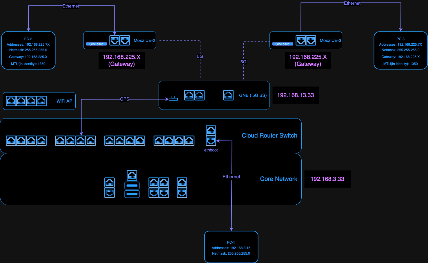
5G/LTE Deployment
Outdoor Setup Example
Figure 1 shows an example setup of the private 5G infrastructure outdoors based on the Ataya Harmony system. The system has several parts:
- The Ataya 5G core network box ("1" in Figure 1)
- Askey small cell base station ("2" in Figure 1)
- MOXA 5G cellular gateway installed on the vehicle top (Figure 2)
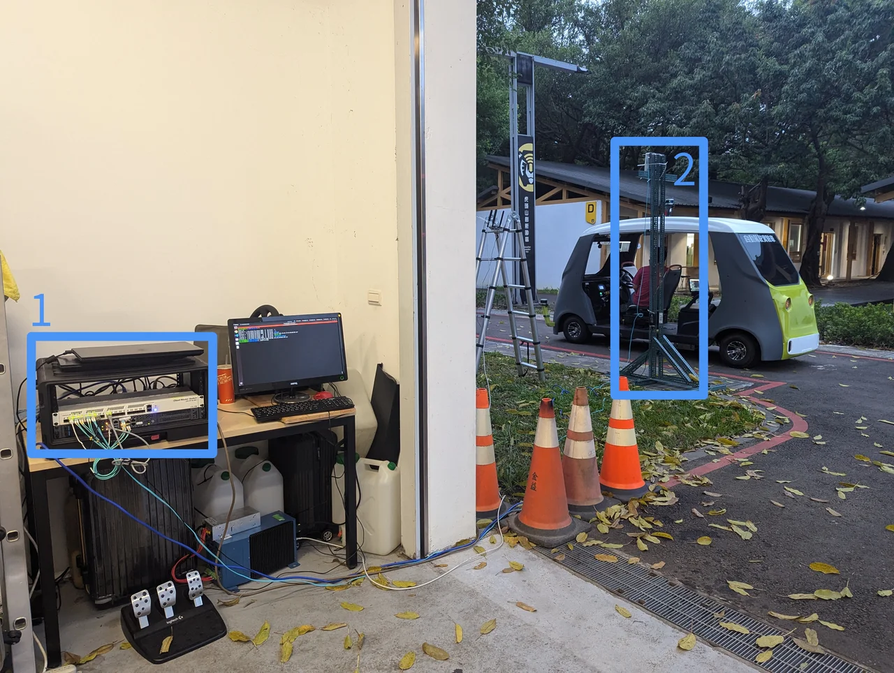
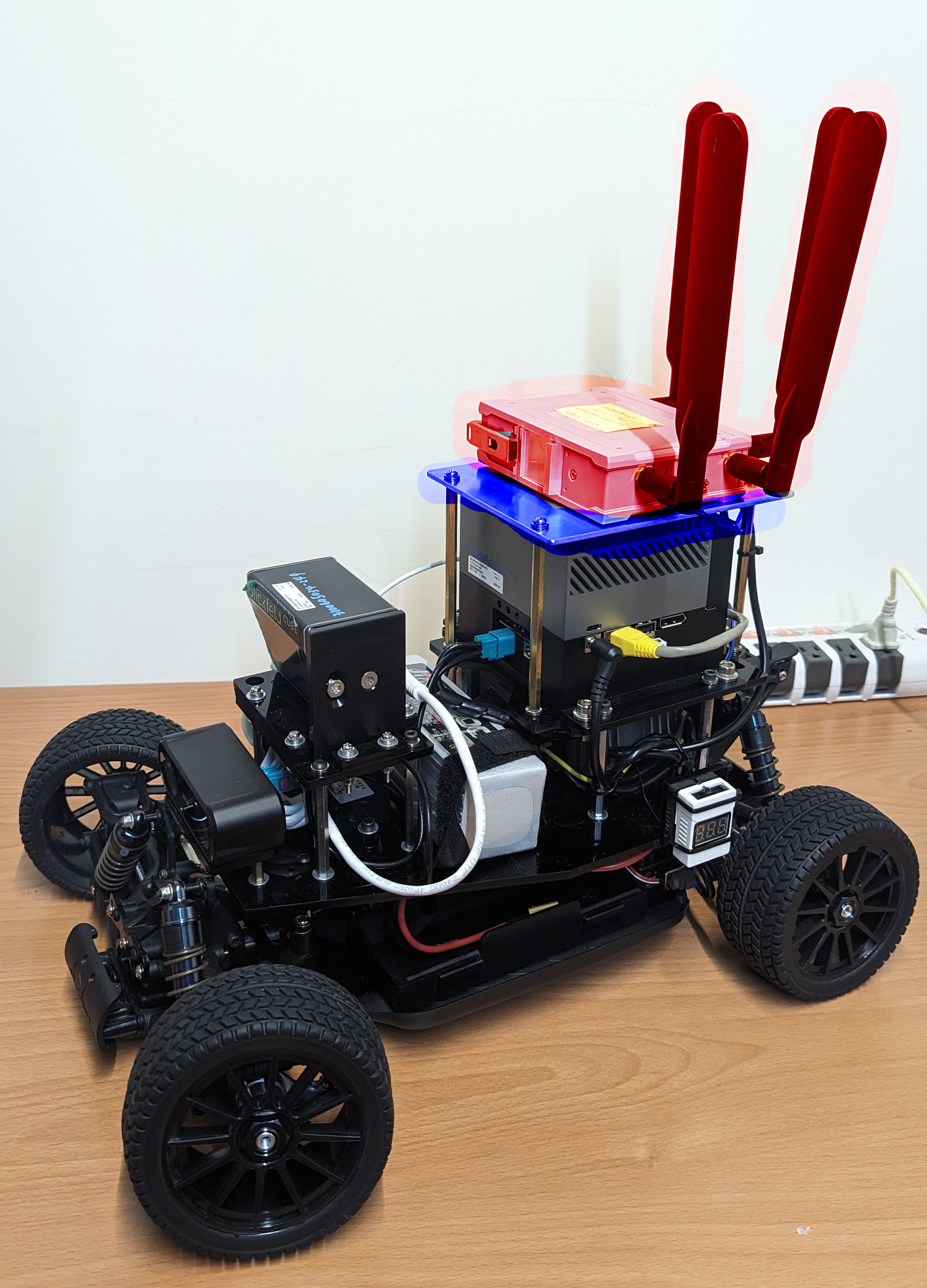
5G signal range can extend up to 600 meters. Compared to Wi-Fi, it maintains stable latency and bandwidth within that area regardless of the distance to the base station.
When setting up 5G equipment, there are several points to consider. First, the 5G receiver in a vehicle must be placed on the exterior of the body and not inside to avoid poor reception. Second, buildings near the base station can affect signal range. Base station antennas usually have directional capabilities, so ensure that the vehicle's activity range is within the antenna's coverage area.
Network Architecture