Building the Vehicle
The recommended vehicle build bases on 16×11×5 inch chassis plus additional sensor and communication mounts, which can be divided into several parts listed below.
The core components includes necessary components to run the Autoware.
- Onboard computer
- Navigation system
- Power supply system
- Powertrain system
- Chassis
The vehicle can be equipped with additional mounts depending on your choice.
- LiDAR sensors
- 5G/LTE communication module
Core Components
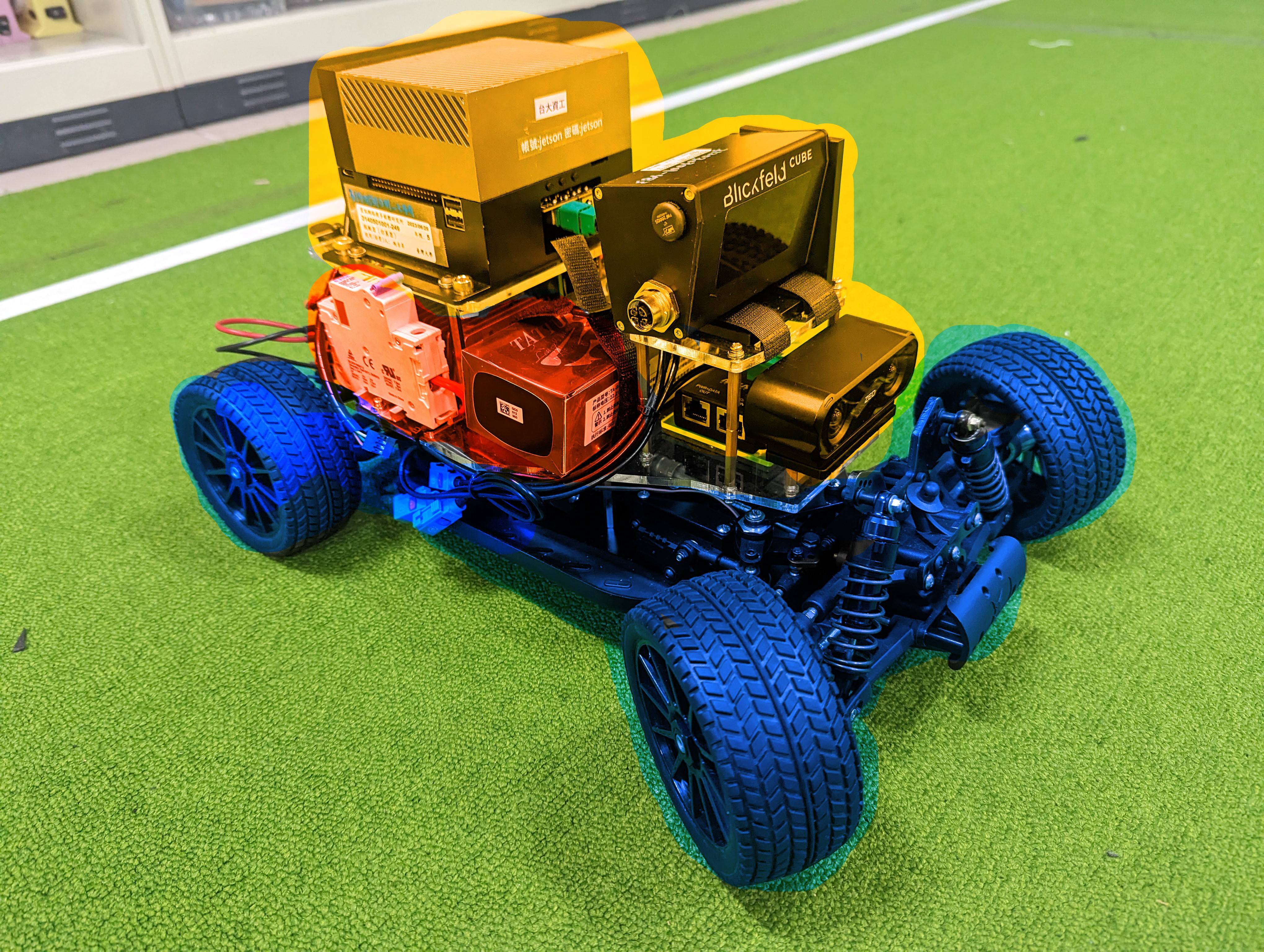
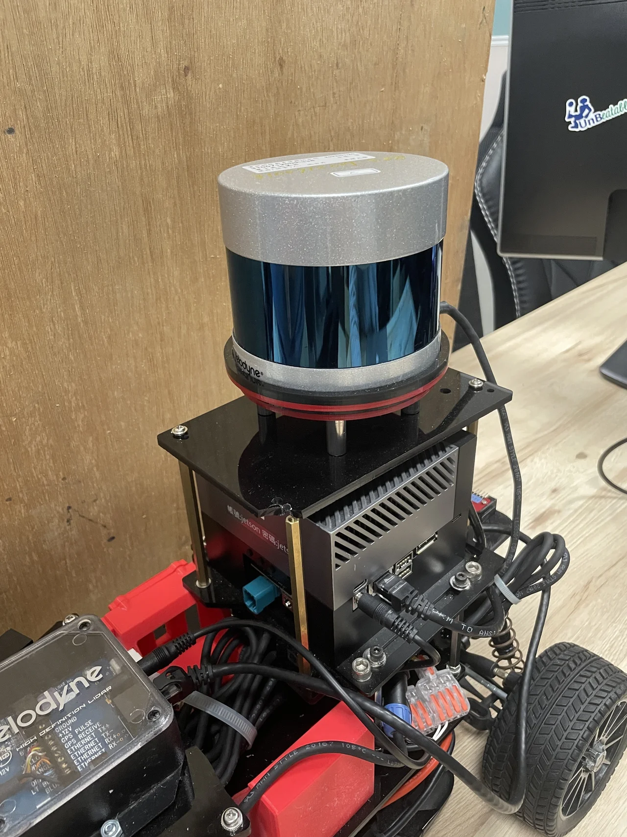
The vehicle has three major layers shown in the Figure 1 from top to bottom.
- Yellow: The onboard computer, navigation sensors and additional mounts.
- Red: Power supply system for the onboard computer and sensors in the yellow layer.
- Blue: Powertrain system and power supply for the powertrain.
By using this vehicle, additional sensors and 5G mounts go to the yellow layer, which power supply comes from the red layer. The motors have a separate battery and power supply in the blue layer due to distinct voltage requirements.
Power Supply System
Batteries
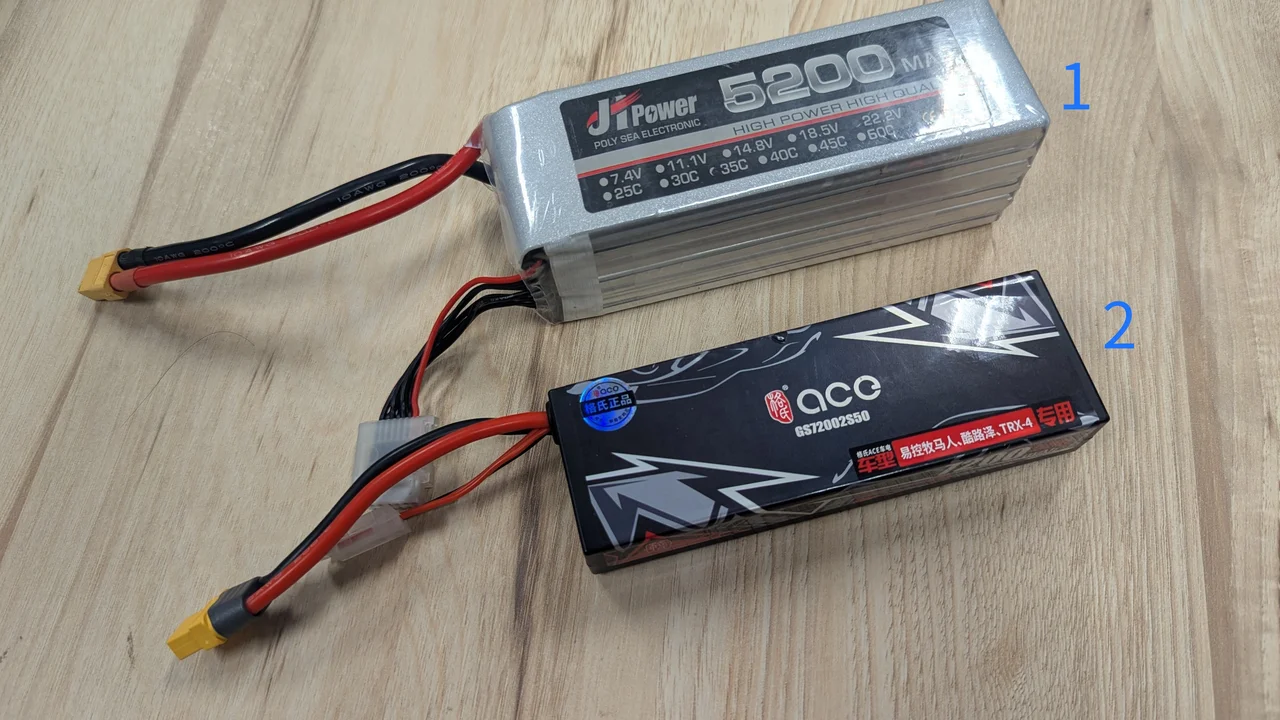
There are two batteries for the respective two power supplies, namely the upper power and lower power. The batteries are shown in Figure 2. The upper power provides electricity to the on-board computer and sensors from a 22.2V 6S battery (1), while the lower power provides electricity to the DC motor and powertrain from a 7.4V 2S battery (2).
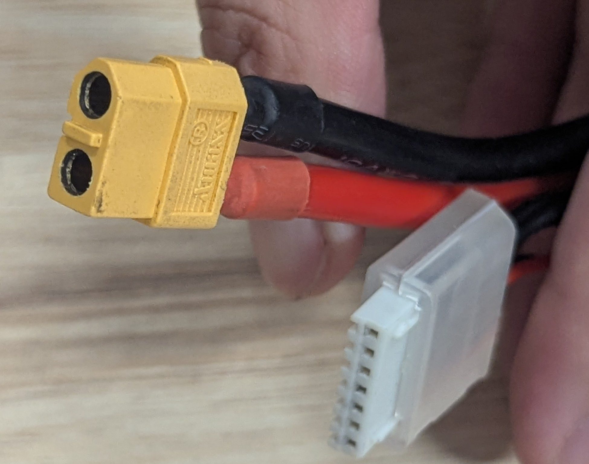
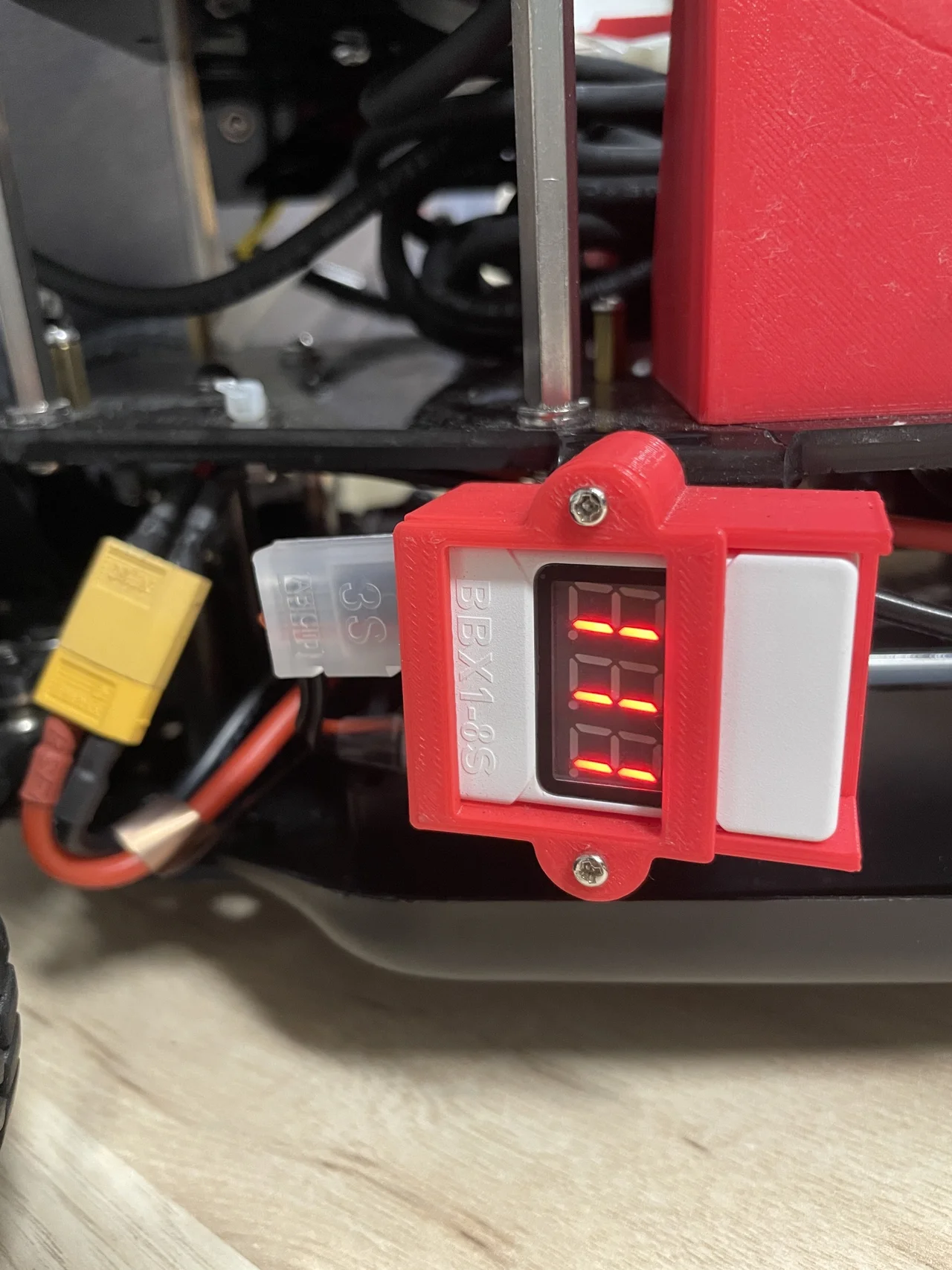
Both batteries have a yellow XT60 power plug and a white JST-XH connector as shown in Figure 3. The JST-XH connector is plugged to a voltage monitor in Figure 4. It beeps when the voltage becomes low.
The Upper Power Supply
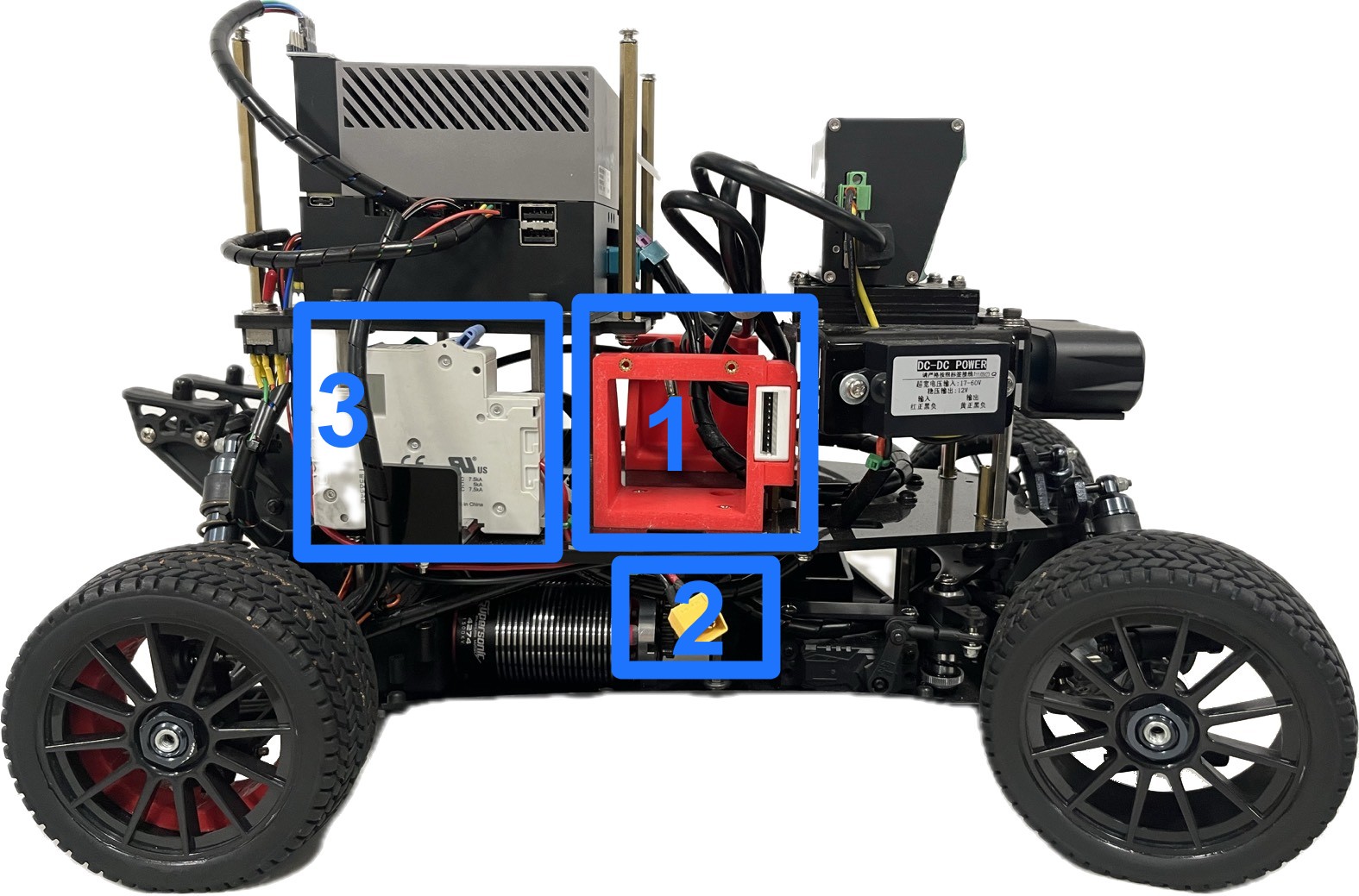
The upper power start up process is shown in Figure 4. First, install the battery on the battery dock. Second, connect battery to the cable. Last, switch on the power supply demonstrated in Figure 5.
Please be cautious that the power switch must be turned off before installing or removing the battery. It's necessary to protect the system from voltage spikes.
The Lower Power Supply
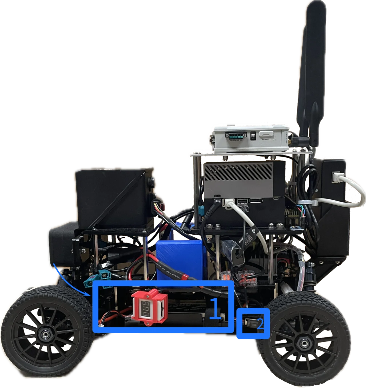
The lower power start up process is shown in Figure 6. The battery is installed in the dock in the bottom layer of the vehicle (1). Then, switch on the power (2).
Docks
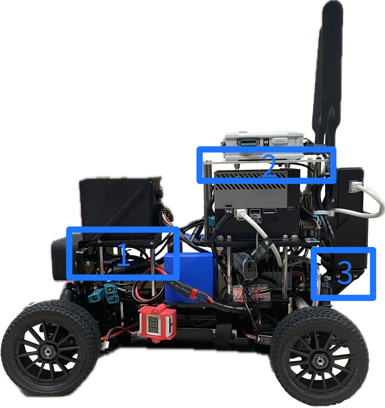
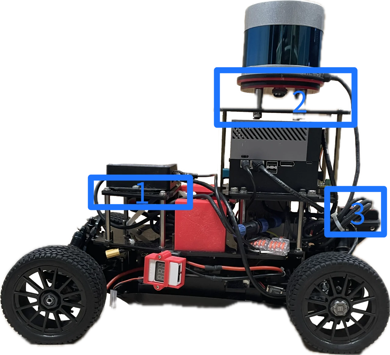
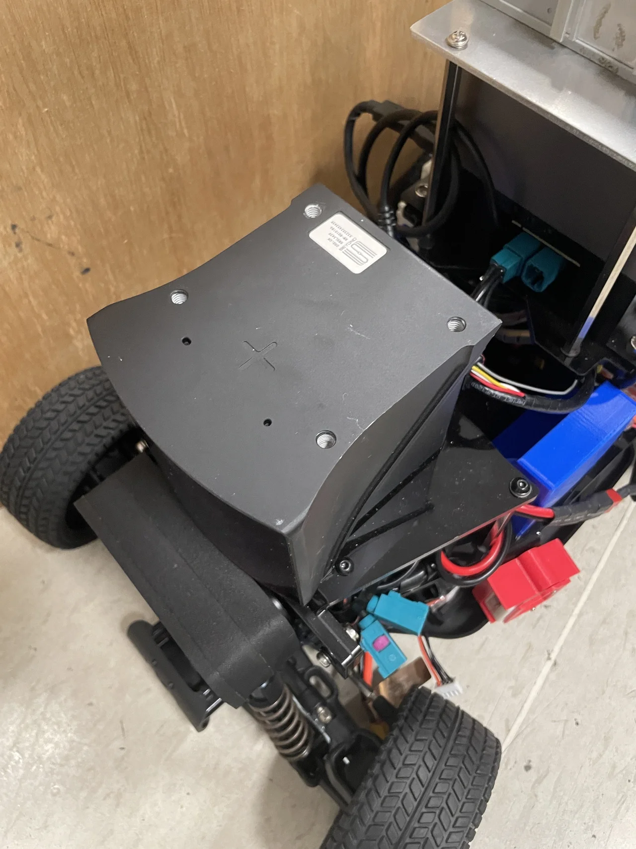
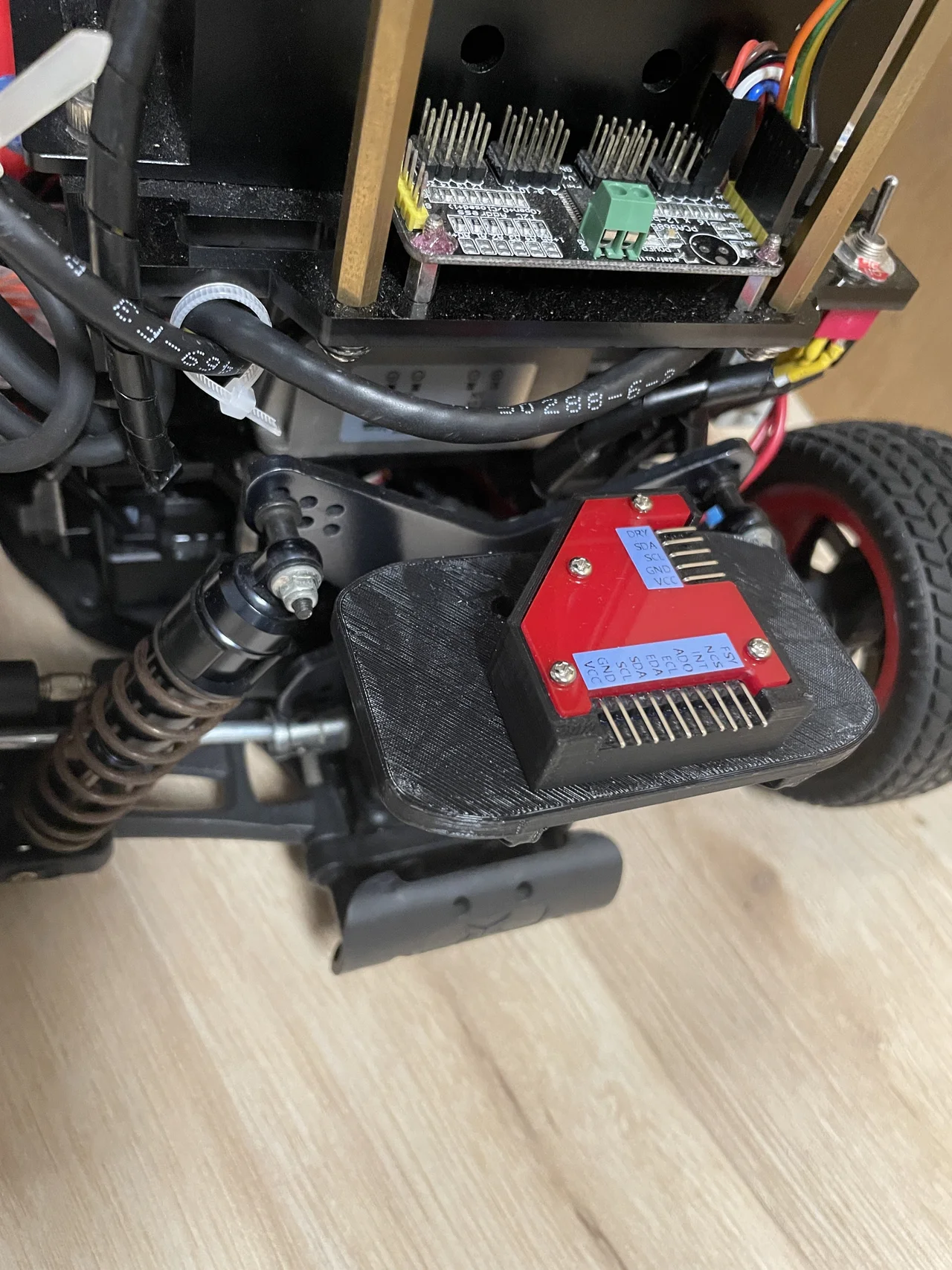
The vehicle has three docks to mount your favorite sensors. The figure below shows two kinds of builds with three docks marked on the figure: (1) the front docker, (2) the top dock and (3) the rear dock.
|
|
The details of two builds are described in the table below.
| No. | Front Dock | Top Dock | Rear Dock |
|---|---|---|---|
| 1 |
|
|
|
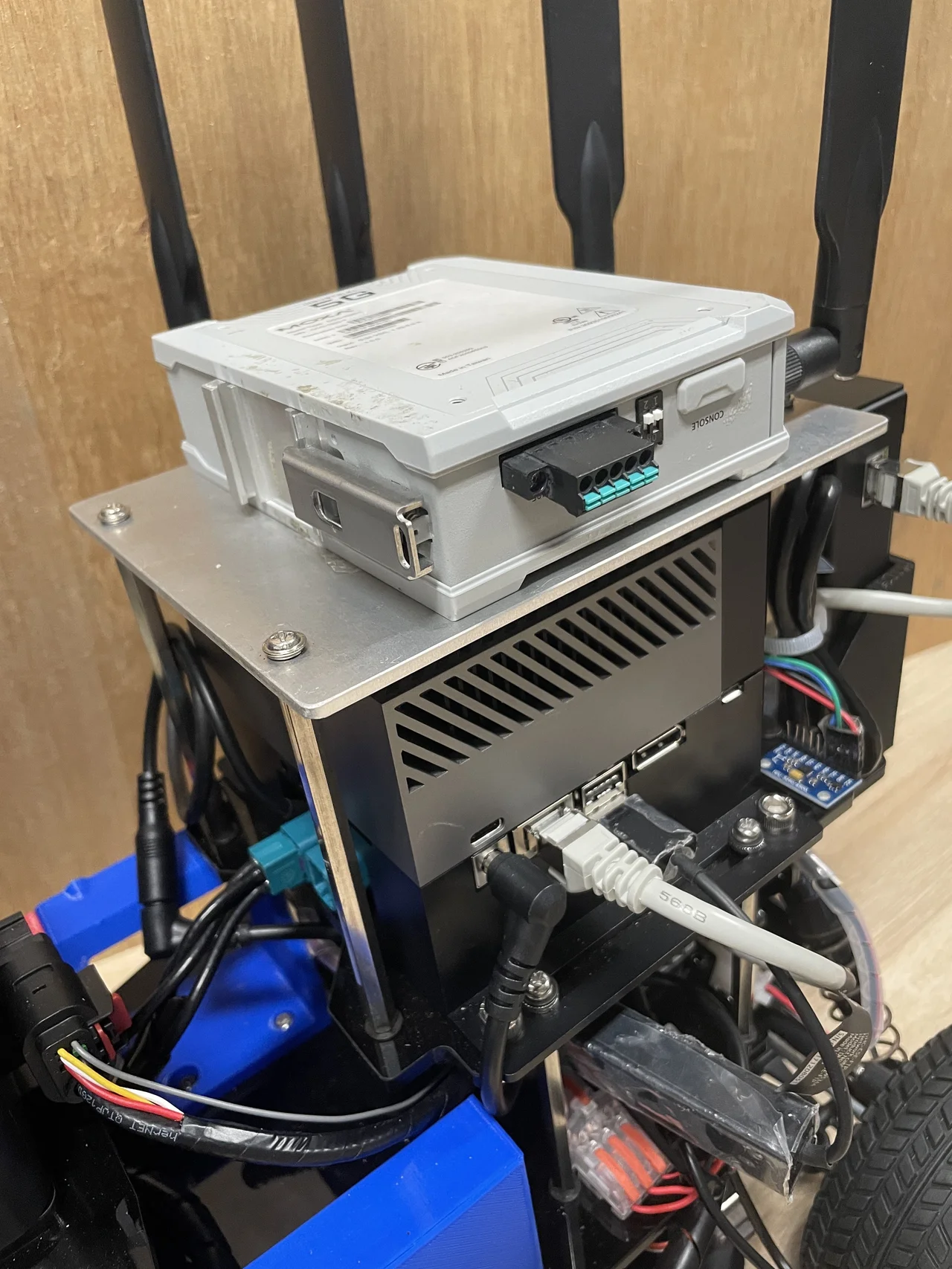
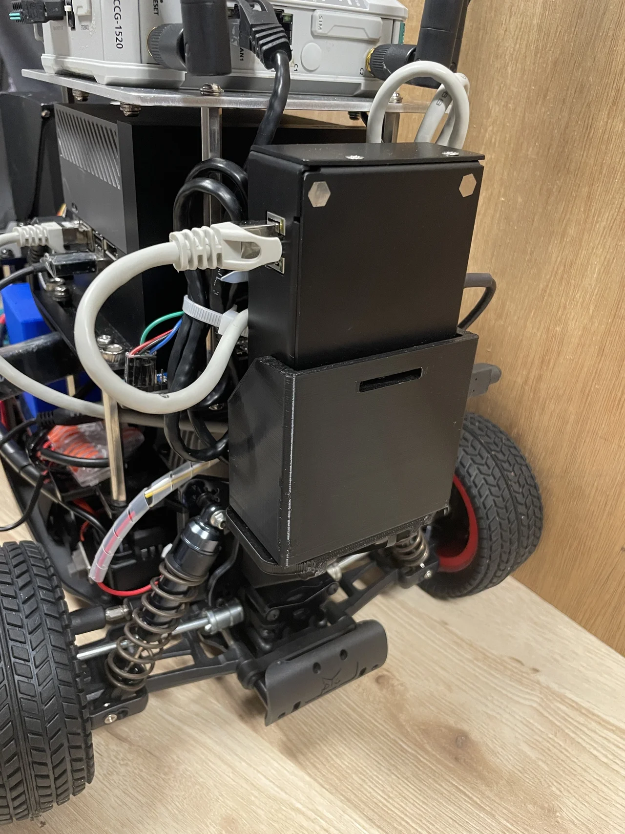
| Seyond Robin-W LiDAR | MOXA 5G Module | LiDAR Ethernet Adaptor | |
| 2 |
|
|
|
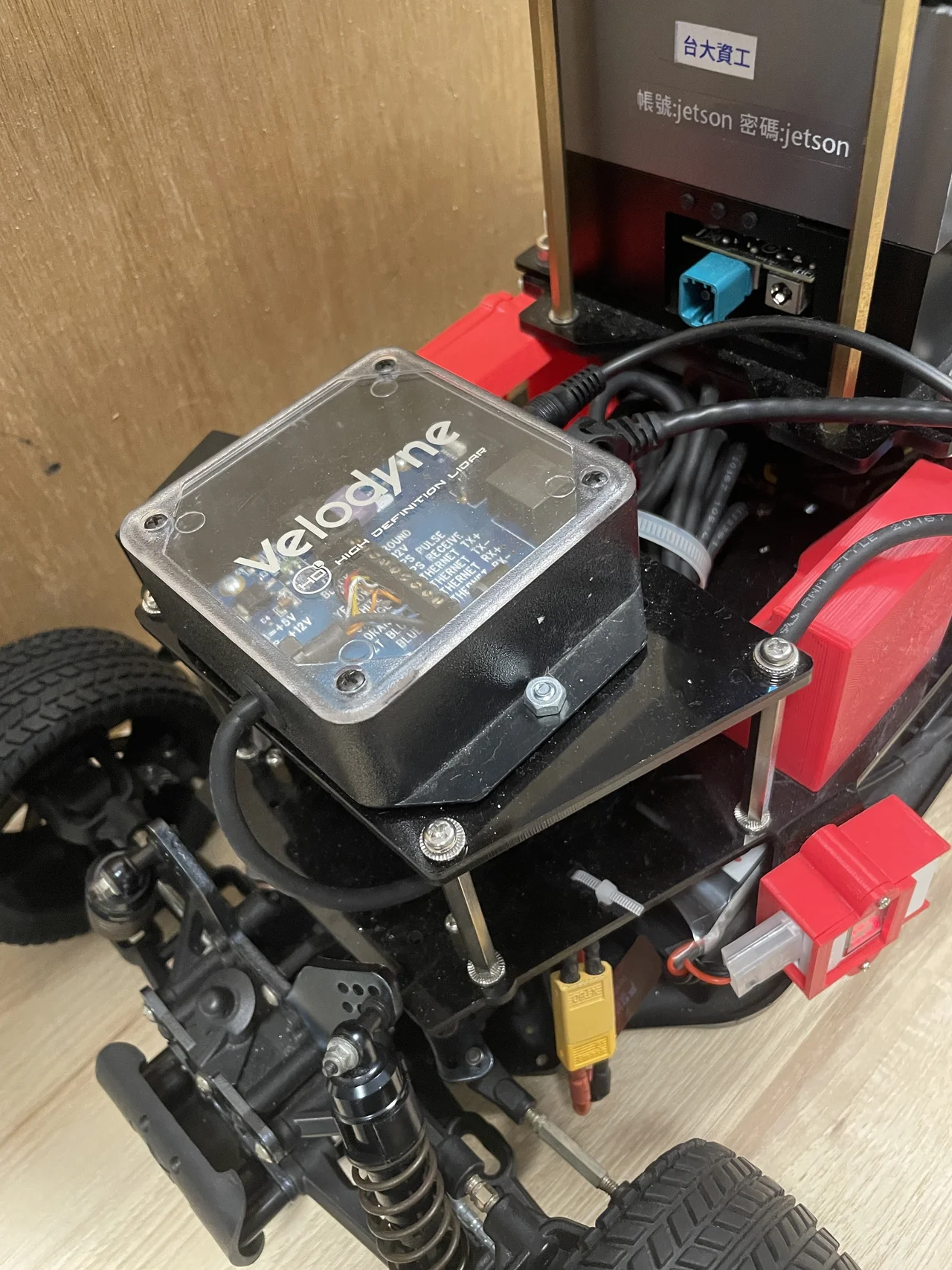
| Velodyne LiDAR Adaptor | Velodyne 32C LiDAR | Navigation Sensor Kit |
Components and Wiring
The vehicle incorporates essential components such as the chassis, body, onboard computer, among others, along with additional LiDARs and a 5G communication module. For detailed information on these elements and their wiring, please refer to the comprehensive guide in Hardware and Wiring.